

Introduction: Asynchronous Serial Communication With AT Commands


If you want to combine two Arduino boards where one collects sensors data and the other sends that data to a server like MQTT, here are some easy code lines that will allow you to do that.
Step 1: Asynchronous Communication
The advantage of Asynchronous Communication is that you don't need the communication being done in sequence, mainly when you define the request code but not the receiving code, being something like:
- Send: Light;
- Receive: 1023.
In the previous case there is the need to wait for the received message because is the only way to make sure that the received value concerns the asked Light value! Context dependent...
On the other hand, if you also code the received value so that you know the respective request, there is no need to wait for the message to be received, you are able to process it at any time! Context independent...
To do so, we need to define our own AT commands, and for the purpose of reading sensors and set pins it may be as simple as:
- AT+A#
- Returns analog pin # sensor value (0,1023)
- AT+A#=n
- Sets analog pin # to value n (0,255)
- AT+#
- Returns digital pin # value (0,1)
- AT+#=n
- Sets digital pin # to value n (0,1)
Step 2: Reading Serial Data
To read serial data this is the bare minimum code:
String inputString = ""; // a string to hold incoming data
boolean stringComplete = false; // whether the string is completevoid setup() {
// initialize serial: Serial.begin(9600); // reserve 200 bytes for the inputString: inputString.reserve(200); }
void loop() {
// gets all serial input while available while (Serial.available()) { // get the new byte: char inChar = (char)Serial.read(); // add it to the inputString: inputString += inChar; // if the incoming character is a newline, set a flag // so the main loop can do something about it: if (inChar == '\n') { stringComplete = true; } }
// starts checking for each full string (string complete) if (stringComplete) { /////////////////////////////////////////////////////// // code to process the received AT command line here // /////////////////////////////////////////////////////// // clear the flag stringComplete = false; // clear the string: inputString = ""; } }
After this, you only need the add your personal code to process the received data in the place indicated in the code.!
Step 3: Processing AT Commands
To use the AT commands all the way, the String functions are very useful, they allow String manipulation of AT commands. All String functions are well documented in the following site:
In our particular case of reading and setting the Arduino Pins, the code goes like this:
    ///////////////////////////////////////////////////////
    // code to process the received AT command line here //
    ///////////////////////////////////////////////////////

    inputString.replace("\r", "");  // removes return chars
    inputString.replace("\n", "");  // removes newline char
    // checks if there are variable request and no command request list
    if (inputString.startsWith("AT") && inputString.indexOf("|") == -1) {

      // processes analog AT commands
      if (inputString.startsWith("AT+A")) {
        if (inputString.indexOf("=") > 0)
        {
          analogWrite(
            (inputString.substring(inputString.indexOf("+")+2, inputString.indexOf("="))).toInt(),
            (inputString.substring(inputString.indexOf("=")+1)).toInt()
          );
        } else {
          Serial.println(inputString + "=" + analogRead((inputString.substring(inputString.indexOf("+")+2)).toInt()));
        }

      // processes digital AT commands
      } else if (inputString.startsWith("AT+")) {
        if (inputString.indexOf("=") > 0) {
          pinMode((inputString.substring(inputString.indexOf("+")+1, inputString.indexOf("="))).toInt(), OUTPUT);
          digitalWrite(
            (inputString.substring(inputString.indexOf("+")+1, inputString.indexOf("="))).toInt(),
            (inputString.substring(inputString.indexOf("=")+1)).toInt()
          );
        } else {
          pinMode((inputString.substring(inputString.indexOf("+")+1)).toInt(), INPUT);
          Serial.println(inputString + "=" + digitalRead((inputString.substring(inputString.indexOf("+")+1)).toInt()));
        }

      // prints commands request list
      } else {
        Serial.println("AT+A#   | Gives analog pin # sensor value (0,1023)");
        Serial.println("AT+A#=n | Sets analog pin # to value n (0,255)");
        Serial.println("AT+#    | Gives digital pin # value (0,1)");
        Serial.println("AT+#=n  | Sets digital pin # to value n (0,1)");
      }
    }
As you can see, it uses many String functions, like the indexOf() function. Basically what this code does is set or return the Arduino Pins values accordingly to the entered AT command that we previously defined.
Step 4: Assembling Full Code
Now we may get together the previous codes and upload it as is to the Arduino board and with complementary code to the client board. The final assembled code is this:
String inputString = ""; // a string to hold incoming data
boolean stringComplete = false; // whether the string is completevoid setup() { // initialize serial: Serial.begin(9600); // reserve 200 bytes for the inputString: inputString.reserve(200); }
void loop() {
// gets all serial input while available while (Serial.available()) { // get the new byte: char inChar = (char)Serial.read(); // add it to the inputString: inputString += inChar; // if the incoming character is a newline, set a flag // so the main loop can do something about it: if (inChar == '\n') { stringComplete = true; } }
// starts checking for each full string (string complete) if (stringComplete) { /////////////////////////////////////////////////////// // code to process the received AT command line here // /////////////////////////////////////////////////////// inputString.replace("\r", ""); // removes return chars inputString.replace("\n", ""); // removes newline char // checks if there are variable request and no command request list if (inputString.startsWith("AT") && inputString.indexOf("|") == -1) { // processes analog AT commands if (inputString.startsWith("AT+A")) { if (inputString.indexOf("=") > 0) { analogWrite( (inputString.substring(inputString.indexOf("+")+2, inputString.indexOf("="))).toInt(), (inputString.substring(inputString.indexOf("=")+1)).toInt() ); } else { Serial.println(inputString + "=" + analogRead((inputString.substring(inputString.indexOf("+")+2)).toInt())); } // processes digital AT commands } else if (inputString.startsWith("AT+")) { if (inputString.indexOf("=") > 0) { pinMode((inputString.substring(inputString.indexOf("+")+1, inputString.indexOf("="))).toInt(), OUTPUT); digitalWrite( (inputString.substring(inputString.indexOf("+")+1, inputString.indexOf("="))).toInt(), (inputString.substring(inputString.indexOf("=")+1)).toInt() ); } else { pinMode((inputString.substring(inputString.indexOf("+")+1)).toInt(), INPUT); Serial.println(inputString + "=" + digitalRead((inputString.substring(inputString.indexOf("+")+1)).toInt())); } // prints commands request list } else { Serial.println("AT+A# | Gives analog pin # sensor value (0,1023)"); Serial.println("AT+A#=n | Sets analog pin # to value n (0,255)"); Serial.println("AT+# | Gives digital pin # value (0,1)"); Serial.println("AT+#=n | Sets digital pin # to value n (0,1)"); } } // clear the flag stringComplete = false; // clear the string: inputString = ""; } }
Step 5: Testing the Serial Communication

Before you wire both boards, you should test the response of your code in each board, to do so, open the Serial Monitor in the Arduino IDE and set it as follows:
- Newline
- 9600 baud
Then type the defined commands to see the response in the Serial Monitor and on your Arduino board. In the next example, is asked the value of the Analog Sensor 1, and then, received the value 1023 for that sensor!
AT+A1
AT+A1=1023
In your final sketch of your Client board, the AT Commands should be posted trough the function println so that a new line ("\n") is added to the end of each AT Command:
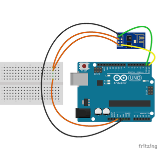
Serial.println("AT+A1");If you are using an ESP8266 ESP-01 board as Client, you just add to he preciously assembled code the following code lines to test the communication between the two boards:
// start previousMillis variable in milliseconds
unsigned long previousMillis = millis();void setup () {
}
void loop () {
// client sends the "AT+2" command each 10 milliseconds if (millis() - previousMillis > 9) { Serial.println("AT+2"); previousMillis = millis(); }
}
These added lines to the previously assembled sketch in the ESP Client board, will turn the led connected to the ESP's GPIO2 pin on and off accordingly to the digital pin 2 in the Arduino board being HIGH or LOW respectively! And thus you had made a successful Asynchronous Serial Communication!
Step 6: Final Notes

NOTE1: Setting the Analog pin value (0,255) is in reality setting the Digital pin with the same number in an Analog fashion, meaning that you activate the PWM feature of the Digital pin simulating this way an Analog variable intensity. PWM is commonly used in servo motors and light dimming. Check first if the digital pin in question is able to do PWM, knowing in advance that none of the digital pins in the ESP8266 ESP-01 are able to!
NOTE2: Set the same baud in both boards so that they are able to communicate, in this case, 9600, knowing that 9600 means 9600 bits/second and each characters has 10 bits, so, in this case, you are able to send 960 chars per second, meaning:
- 1 millisecond per char at 9600 baud!
In the case of "AT+2=0" that in reality is converted to "AT+2=0\r\n", you send 8 chars, so it takes 8 milliseconds, and this is why you may send "AT+2" each 10 milliseconds!
NOTE3: While the println() and the while() serial reading functions don't interrupt the loop() function, the String functions do, mainly the replace() and the substring() functions, where in this case the AT Commands processing takes around 0.1 millisecond per character, so 10% more should be accounted! This way you shouldn't send (or receive) more than one character per 1.1 milliseconds on average considering the needed time to process the AT Commands.


