

Introduction: A Wireless Smart Home (was: at Home Simulator and Alarm With Arduino or Atmega328 (updated May 2016))


Note: There now is an android bluetooth control app ibble for this project
Note: Though this started out as a project simulating my presence at home, it has grown into a smart home, hence I retitled this Instructable
When people are on holiday, or sometimes even just gone out for a night, their homes are vulnerable for burglars.
So, people tend to have timers on one or two lights to switch on when it is dark so burglars might be fooled in thinking the occupants are still present.
Burglars are not stupid. Especially when one is away for a longer period, it is kinda odd that the lights switch one well, like clockwork. This is even more suspicious in the late fall or winter when it gets darker earlier but without the lights being switched on earlier.
I was faced with a family member going away for a prolonged period who left his house in my care.
So I wanted to quickly put something together that would do a better job than a timer clock., Something that had more variation, would make things look more natural.
Because I didn’t want to mess with too much wires I decided to make it kinda wireless. It helped that I had some 433 MHz Switches and a cheap transmitter module.
My basic idea was to Switch a main lamp in the living room, a lamp in the study and a lamp in the bedroom. The time for the system to switch on needed to be variable, depending on the light. The lamps should not switch on every day at the same moment and there needed to be a natural flow from the living room to the bedroom at sleeping time. An Arduino seemed like the perfect instrument and and as it was I happened to have a few Pro-mini's (that is to say... clones)
Ofcourse it is possible to do this with any arduino.
Anyway, as said, I quickly put something together on a small breadboard and put that to work, but then I wanted one for myself as well, a bit more permanent, and I added features to that.
So I will describe two versions
The very basic version just has a pro Mini, with a simple DS1307 RTC, an LDR, a 433 MHz Transmitter and 3 remote Switches for 3 lamps. The amount of lamps or other devices that on wants basically depends on the amount of Remote Switches you have.
The advanced version has a larger number of Remote Switches, it has sound detection, an internal relay, IRleds, a dog barking, a voice message, bluetooth, a buzzer, a fakeTV, and moving puppet.Update may 2016: this has now grown into a 23 RF switched channels + IR circuit, regulating many functions in and around my house
I will discuss the basic module first
B.O.M.
Basic
Arduino pro mini/ (or a barebones Atmega328 with bootloader)
DS1307 RTC module (or DS3231 module (see text below))
433MHz transmitter module
17.4 cm stiff wire or or preferably a coil loaded antenna.
LDR
3 x 433 MHz Switches e.g. ELRO 440 or a SelectRemote or any other
A USB to FTDI module comes in handy to do the programming
Just a few Remarks:
In its basic form the RTC is a DS1307. I know there is the more accurate 3231, but that lacks the Non Volatile RAM that is needed to store various statuses.
It is possible to use a 3231 module if it is combined with en EEPROM, but that requires a slight adaptation of the code (I do this in the advanced version). I know the Arduino also has EEPROM where one could store statuses, but the writing to the Arduino EEPROM is not infinite. Therefore I try to avoid it, hence the DS1307. The DS3232 also has NVR
Step 1: Components: General Remarks on Cost & Self Built
Nowadays, many prefabricated modules are available fairly cheap. Building from discrete components, though fun, becomes more and more a challenge to do cheaply.
I still do, because I have components laying around, but to give an example: I paid I think 4 euro for the Atmega328 chip less than a year ago. That is only the unprogrammed chip. So to use it I have to get a crystal, an IC socket, a stabilizer, connection material, a switch... and then I have to all solder it together.
I have bought complete Arduino Uno's for 2.50 euro and a pro mini for 1.60 euro. Do the math.
On my perfboard there is a relay. I think that costed me 3 euros. Add to that 1 transistor, 1 diode, 1 resistor and it adds up. For 1.80 euro, I can get a double relay module, including signaling LEDs.
Now in other parts of the world that might be different, but certainly if you live in the west you may want to think in modules rather than components and order themat DealExtreme, Aliexpress or Banggood
Step 2: Building the Basic Version


The circuit is quite easy. It is an Arduino Pro Mini with 3 extra components:
A DS1307 RTC
A 433 MHz Transmitter
An LDR
The RTC is an I2C module that is connected to SDA (A4) SCL (A5) and Vcc and ground.
The 433 MHz transmitter is just a cheap transmitter that costs about 1 euro together with the Receiver (that we are not using). It attaches to Digital Pin 7 and ofcourse to Vcc and Ground
The LDR is a 10k type (but that is not so critical). It attaches between A0 and Ground. The "normal" protocol seems to favor variable resistors such as an LDR to be between Vcc and an Analog input but I a not doing that because I want to use the internal pullup resistor as voltage divider. That saves a resistor. Therefore the LDR is between ground and A0.
With regard to attaching the RTC to SDA and SCL on an Arduino Pro Mini there is a slight problem. Usually the pin A4 (SDA) and A5 (SCL) are in an odd configuration that prevents them from being used on a breadboard. As there are many pro mini clones, it is hard to say where exactly you will find those pins, but it should be quite obvious on your borad. You will have to approach the A4 and A5 from the top though. Do not solder any pins sticking out at the bottom 'for breadboard use' as that will cause problems.
Usually, if you buy a pro mini clone it arrives with a number of male pins that still need to be soldered in. Often it will have 6 90 degrees angled pins for the FTDI programming header. My advice would be not to use those but to just use a 6 pin straight FEMALE or MALE header depending on what your USB-FTDI adaptor needs.
Wether you use male headers or female headers for the other pins and whether you solder these at the bottom or at the top depends on your situation: if you want to keep this on a breadboard then male headers at the bottom are yr choice. Also if you want to build it on stripboard or perfboard where you will just plug in the pro mini, headers at the bottom are your choice.
if you just want to plug in your connections from the top, male headers at the top will prove very handy.
Step 3: The FTDI Header


The pro mini does not have a USB interface but it does have an FTDI header for programming.
Therefore you will need a USB to FTDI adapter.
These are quite cheap nowadays.
I have attached pictures of two modules, one from Aliexpress and one from Adafruit. Make sure you get the 6 pin version, not the 4 pin version or you will have to do the uploading by pressing the reset every time
As the FTDI header is standardized, the pins of your adapter should nicely line up with the corresponding pins on your Pro Mini. Make sure that you have matching connectors (male to female) if not then just make an adapter from two female headers or male headers soldered back to back.
As there are many clones of the Pro Mini, there is no garantee that they all have a standard FTDI header ( but I haven’t come across one that doesn’t), so it is always good to check.
The only thing that can be confusing are Rx and Tx. Normally a Tx always has to plug into an Rx and vice versa. But in order to 'make it easy' some manufacturers switch the labelling for the Tx and Rx pins in their silkscreen so the Tx is labelled Rx, indicating 'it goes to the Rx pin'.
Anyway, just saying it always is a good thing to check.
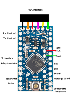
On your Pro Mini if you have the edge with the FTDI header pointing upwards it goes from left to right as follows:
Ground Ground Vcc Rx Tx RST
To make it easy, these pins also have a standard colorcode assigned with the left ground pin assigned 'Black' and the right RST pin assigned Green (check my picture)
Beware!!! On your Pro Mini these may be in the silkscreen as 'BLK' and 'GRN' Dont make the mistake to think 'GRN' is 'Ground' as it is NOT
On your USB-FTDI adapter if you have the header pointing down, the labelling should be as follows:
Ground, CTS, Vcc, Tx, Rx, DTR
The CTS is the 'Clear to Send' signal and you do not really need that, but connect it anyway.
The DTR is the 'Data Terminal Ready' signal. It connects to the RST pin on the Arduino and issues a reset at the right moment. If you only have a 4 pin USB TTL adapter, without the DTR signal broken out, you will need to press the reset button yourself at the right time.
Step 4: The Remote Switches


This system works wireless through a small 433 MHz RF transmitter that sends commands to commercially available Remote Switches.
To send the proper commands I am using an extended version of the 'Fuzzilogic' 'Remote Switch' library.
In the program I have included code examples for some readily available Commercial Remote Switches.
The Transmitter module is rather cheap but works well. It is necesary however to use a decent antenna.
I have had decent results with just a 17,4 cm straight wire attached to the transmitter, but a coil loaded antenna gives better results and is simple to make. Check out the picture for details
Step 5: The Basic Code for Use With DS1307 RTC
You will find the code on codebender (See bottom of page).
Basically what the code does is after defining its basic parameters is to lopp through a bunch of 'IF' conditions in which the current time is checked against some set time values and if met, switch a light ON or OFF.
The status of the lights gets stored in a variable to work with as well as in NVR RAM as back up if there is a power interruption.
The use of NVR RAM means that you are bound to using the DS1307 RTC module.
You have two other options to use as permanent storage: The EEPROM of the Arduino, or the EEPROM that is on most RTC modules.
For several reasons initially I chose for the NVRam, but in hindsight it would have been better to chose for the EEPROM present on most RTC modules such as the DS1307 or the DS3231 as that makes the code a bit more universal. I have rewritten that for the more extended program. Use my 'Extended program' to get flexibility in using an RTC DS3231 or DS1307
The condition testing takes the following shape
IF currenthour ==x AND currentminute+random ==y AND lightstatus==OFF
THEN Switch on Light
Write lightstatus to ON
udate NVR
I add the randomfactor just to make it look more natural. Always having yr lights go on at 9:00:00 pm signals 'I am away'
The code has several print statements but tehse ofcourse are only of use if you have a bluetooth module atteched or a terminal.
You can make the code much more sophisticated by checking for say the day or the month and switch the lights longer or shorter depending on the month or whether it is a weekday or a weekend.
The Extended version (see later on) has much more functionality and will run on the 'Basic Version'
Attachments

Step 6: The Advanced Version


The advanced version is advanced in Hardware as well as in Software. The hardware is extended with several 'modules' to chose from. The software is extended to support this but also has a lot of new functionality like detection of Day Light Savings Time and logging of things.
I have added the following hardware:
With Infrared transmitter
20 Ohm resistor
1 k resistor
2 IR LED's 940 nM (I use the IR204 and SFH485)
1x BC547 transistor
With NTC
an NTC
With Dog Barking
MP3 module + Remote switch
With Internal Relay
1x BC547 transistor
1k resistor
1x1N4148 diode
V2340-A0001 B201 Relais or other 5Volt relay
With Sound detection
SoundBoard with digital output
With movement suggestion
Check this instructable
with 433 MHz RenoteSwitch
With TV simulation
Check this instructable
with 433 MHz RemoteSwitch
With Bluetooth
Bluetooth module HC05 or HC06
With a Spoken Message
Digital Voice recording Board
Just a few Remarks:
Rather than a DS1307 RTC I use a DS3231 RTC module that has also an EEPROM. I use that EEPROM for storage of several status flags. If you have a DS1307 module with EEPROM that ofcourse is also useable.
Step 7: Building the Advanced Version


Like the basic version, this version can be put on a breadboard, but as I want a more permanent contraption, I built it on veroboard. I could have used an Arduino Pro Mini but I opted for a bare Atmega328 chip in which I burned an UNO bootloader.
There is not much I can say about building it on veroboard other than that it is just a matter of diligently making the point to point connections. Make sure that there is a bit of slack in your wires as later on you may decide to use a pin that is buried under a bunch of wires.
What I didn't do with my version, but am doing with a new version, is to solder a row of pinheaders next to the Atmega chip so I can always approach a pin from the top as well.
Step 8: The Extra Hardware


The IR module
Originally I included this module to Switch my TV On and Off during my absence, but there are better ways for that. So for me it didn’t turn out to be very useful, but for you that might be different. It is basically a transistor that drives two IR LED's. The IR LEDs I am using are the SFH485 and the IR204. The former is a 5 mm 880 nm LED, the latter is a 3 mm 940nm. (note: I am now using it to switch TV channels with my smartphone)
Pay attention: the IR204 has the short leg as it's cathode -as is normal for LEDs- but the SFH485 has the longer leg as its cathode. I use both LEDs in series with a 20 ohm resistor, on 5 Volt that gives about 100mA LED current, As the LEDs are used with PWM, they probably will be fine without resistor. The famous "TV-bgone" circuit does that for instance, where they do not use the LED's in series and also do not use a resistor. As said I use LEDs with different wavelengths. I did that because that is what I had. Generally though 880nM is the best choice for infra-red remote control of TV's etcetera. I have both Diodes peeping through holes in the front of my casing. It is driven by Digital Pin 3. I frive the IRLED's with almost 100mA which is their maximum Continuous Forward current. However, it is possible to drive them with more current as they are not driven continuous. If they get a 50% dutycycle signal, in theory one should be able to drive them with 200mA. The IRremote and IRLib libraries drive the signal with a 33% dutycycle, so in theory 300mA might be possible. The IR204 can take 1Amp peak current if the dutycycle is less than 1% on a pulse of max 100us.The 90mA I use to drive them however already good results.
NTC
As the DS3231 RTC module that I use has a temperature sensor, I can read the temperature from that. It is however within my casing and doesnt vary that much. I added an NTC at the outside so my device could spot a possible temperature drop (say if a window broke in the winter) It attaches to Analog Pin 1.
Dog barking
A rather quintessential part of an anti-burglary system. Nothing keeps burglars away as much as a dog. I had quite a journey on this. First I used a ready made Dog bark module, bu that sounded pathetic. I tried some other things until I decided on a cheap MP3 module that plays files from an SD card. I put some vicious dog sounds on it and done. At first I wanted to switch it on with a relay, but I figured it is easier to have it have its own PSU and switch that on and off remotely with a commercial Remote Switch
Internal Relay
I added this relay in order to switch on the dog bark module, but I decided on another way to do that. Yet, you may have use for it. It is simply a 5 Volt relay driven by a BC547 transistor. I made sure I picked a relay with standard 2.54mm (0.1 inch) spacing, so it would easily fit on veroboard. I put mine in an IC socket. It is triggered by Digital Pin 4
Soundlevel detection module.
This is a microphone module with a noise level (digital) output. I use it to detect unusal soundlevels when I am not home. Modules like this are available for about 1.50 euro. It attaches to Digital Pin 10.
Message Module
This is an ISD1820 digital voice recording module that can record your voice and play it back. I use it to remind me to put the trash out on a certain day, but you could also use it to play a message ("I have got a gun!!!) if there is a suspicious noise detected.
This module can be triggered by a High Level and it will play the message as long as there is a high on the required pin and it can be Edge triggered, meaning it only needs one short pulse to start playing. I use the latter method and I generate the pulse on Digtiatl Pin 12.
Movement module
Other than with a barking dog, burglars will most likely also pass by your house if they see activity. I have constructed a kind of moving cardboard figure that is driven by an attiny85, a steppermotor and a servo. It is the subject of an other instructable. I got the inspiration from the Movie 'Home Alone' where McCauley Calkin put cardboard figures on a grammophone in order to make the Burglars think there was a party going on.
Obviously. the essence of this 'puppet' is that it is placed behind a curtain and that the shadows it casts are what will (hopefully) deter the burglars.
Fake TV
Leaving on a TV is a deterrent, but it consumes quite some power. Also, leaving on a TV during a prolonged period of time has the risk of it catching fire, which is bad enough when you are present, but then you can take action, but is even worse when you are away and your house is burning down. There is a device called 'fake TV' that imitates a TV with different colour LEDs. I have heard mixed reviews about it, but it might be worth its 25-30 USD price tag. I have not seen it in Europe (except for the UK with a 20 GBP price tag), But it is available at Aliexpress for 12.50 euro I may try and make one myself one day, perhaps one of those flickering candles, modded to have some more LEDs might be a cheap solution. The fake TV should be placed so it can project on something like curtains. The may not be too thick or else one wont see anything, but also not to thin so one can see it is nit a fake tv.
On instructables there are some projects with ambient light. perhaps that would also work.
The forum at AdaFruit also shows a 'Fake TV' with an Arduino. I have built one myself fairly cheap. Another pretty neat one is this one from John Bush
The fakeTV I have only needs power to start working, so also this one I connected it to one of my Rf 433MHz remote Switches and switch it on and off at a desired moment,
Many commercially available fakeTV's will react to light and then play a set time. I found that a bit less flexible for my needs and that is why i opted to build one myself (+ it was a lot cheaper)The Fake TV is switched on remotely with a Remote Switch.
External Relay
I have made a remote controlled 5 Volt Relay module that I use to switch some solar power. As it is fed by a solarpanel, I coul;d not use one of the commercially available 230 AC volt Remote Switches. I currently have no description of it in an ibble so stay tuned, but then again, you may not have use for i.
Bluetooth
I have added a cheap bluetooth module in order to be able to give some input to the circuit and to gain some information from it. There are plenty of tutorials on how to connect a bluetooth module to an arduino, difficult ones and easy ones, but it is in fact real easy. connect Rx of the module to Tx of the Arduino, connect Tx of module to Rx of Arduino. Connect Vcc and connect groundt and you are ready. Just remember that if you want to upload a sketch, you need to remove the bluetooth module or it will interfere with the uploading process. Both HC05 as HC06 modules worked for me
Step 9: The Advanced Code
This is the more advanced code. It no longer uses NVRam that would confine it to the DS1307. It can now also be used with the DS3231 or the DS1307 as it uses the EEPROM present on most RTC modules.
It is a working code but still in progress, that is why you may find a lot of commands that are commented out. It will gradually be cleaned up though. Though it all started as an 'athome simulator' I found its use so practical that I keep it working even if I am at home myself. I have an option though to set my absence, so it can decide NOT to sound an alarm if it hears noise.
It has the following extensions as compared to the basic software
- 16 remote switches as opposed to 3 (use for lamps as well as a barking dog sound as well as a moving figure behind my curtains.)
- Internal relay to switch 'something' (on D4)
- IR transmitter
- Bluetooth as an option.
- Keeps track of Daylightsavingtime for the EU. If you live outside the EU u need to adapt the algorithm
- Calculates sunsetapproximation
- Can ring (my) doorbell
- Operates a buzzer (on D13)
- Operates a soundmodule for spoken messages (on D12)
- Has a microphone module (on D10)
- It reads the temperature (if you have a DS3231)
Attachments
Step 10: The Advanced Code: Description
Initially the code sets up a lot of variables and constants. It defines a number of macro's especially for the specific Remote Switch commands. I do that so it is easy to change those at one location in case you are using different Switches.
In the setup, it sets up the Serial port and the time. It then reads the EEPROM of the RTC module to see if at power ON, some lights or devices should be switched on and it does so. I do this so in case of a power interrupt and restart, the controller still knows what should be on and what not.
The loop checks the Serial Port for input (from a bluetooth module) and takes action if input is found. If not it updates the time.
Then basically what it does is cycle through a number of IF statements to see if it is time for some action, Switch a device ON or OFF
If a device needs to be switched on, it jumps to the corresponding subroutine/function, it sends the specific command and it updates the statusflag and writes that to EEPROM. It sends the specific command via a macro such as "HuiskamerAAN" (Living Room ON). you need to make sure that the definition in the Macro's matches the command that your Remote control switch needs.
Apologies for keeping the macro Definitions in Dutch, but I already used the English term for the Functions: I.e. The Function 'LivingRoomON' uses the macro "HuiskamerAAN". Under the Macro definitions you will find exactly what is what in English.
While it is looping, the program also continuously checks if it maybe is already the right date for DaylightSavingstime or, if it IS already DST, whether it is the right date to switch that Off.
It also keeps track of what date it is so it can do an approximation of Sunset and Sunrise time. It Will switch on the light in the living room about half an hour before sunset, unless it is already dark sooner (overcast sky, thunder, whatever) then it will switch on the lights sooner.
It does this by reading an LDR. You need to set the level for that to your own situation.
With regard to DST calculation and Sunrise approximation, these are valid for my location (in NW Europe) you need to adapt those for your situation (and maybe you do not have DST)
With regard to the time variables a call like "now.minute()' reads the RTC right away.
However I let the loop constantly update the time variables like this:
j = now.year();
mo = now.month();
d = now.day();
h = now.hour();
m = now.minute();
s = now.second();
So throughout the program it is OK to use either 'h' or 'now.hour()' to get the hour.
The only difference is that using 'h' probably will be a tadd faster than using 'now.hour()' but 'h' might be a fraction of time behind. I think the loop is cycled about 150 times a second so if I update the variables at the beginning of the loop and use them towards the end of the loop, I may be 1/150 th of a second behind. That doesn't really seem like a problem to me
Step 11: Future Expansions


Though originally planned just as a device to simulate someone being at home, it more and more has grown into a home automation (e.g, taking care of my hydroponics as well :-) )
So I thought I would add a laser tripwire as well. I already have one, but as I like to have it wireless as well, I built a small attiny based device that monitors a laser tripwire, a real tripwire as well as a proximity sensor and a vibration contact and sends a radiosignal to my 'Athome' circuit. That does require a receiver+ antenna in my casing as well which might outgrow its size. Another possibility is to have that circuit create a loud noise that will be picked up by my microphone, or to not send the signal to my base unit, but let the sensor circuit switch the desired rf switches that are already in place.
I have added an Android app to control the unit
In its current form the Athome simulator has been working at two locations for almost 3 years now without any problems or break ins :-)


