

Introduction: Atari SX2600 - a Fairly Complete Atari 2600 Emulation Console


I'm certain that several of you old-console & case modding fans have seen a certain Atari 2600 case mod on the web- One that had managed to earn a fairly prominent autograph- which, to me, proved to be a total let-down. The 'Heavy Sixer' used was butchered to the point where not only did the unit no longer resemble an authentic Atari, but judging from the photographs posted, it seems that one cannot even plug an Atari joystick into it.
Whats the point ?
Anyway, I felt I could do better, so I worked to build a fairly modern system out of an Atari, while keeping its, erm.. Atariness..
The above photos are the result :
So, if you want to try your hand at this - follow along !
Step 1: What You Need, and Some Advice -

There are two things I learned while doing this project :
A ) An Atari 2600 has very little room inside.
B ) Patience is required.
So, once you collect your hardware, make certain to plan every step, measure every cut, and dry-fit every component before committing. Otherwise, it is likely your result may be less than satisfactory.
What is needed.
One or two donor Atari 2600 units, (Not a 2600jr -too small) preferably of the same vintage and design.
Assorted hand cutting tools, as well as rotary (Dremel) tools.
ITX form factor mainboard, preferably with a good integrated graphics solution, and HDMI output.
'Slim' optical drive
3.5in hard disk
External power supply
*1U compliant fans, heatsinks etc.
Internal USB bracket
Assorted momentary contact switches ( i'll go into more detail later)
Atari joysticks, paddles, USB cabling
Retrolink Sega Genesis cable
Source of donor plastic ( I used a cheap plastic three-ring binder I got at Walmart )
A donor PC keyboard
electronics breadboard. I used scraps I had in a drawer.
Wiring, solder, hot glue, rubber cement, super glue.
Sandpaper
A pair of cheap donor USB optical mouses ( $8 each at Walmart )
Decocolor Orange paint pen
Small silicone rubber pads to use as standoffs (also from Walmart)
*1U compliance is very important, without it, this project will not work.
Lets begin !
Step 2: Gut and Clean Your Donor Atari


So, you have an Atari ?
If its anything like the one I ended up with, its filthy, and barely working. Remove the four screws holding the case closed, and pull the top of the unit away from the pan. Inside you will find the mainboard, remove it, and on the mainboard, you will notice circular black foam rubber pads on the switches. Take them off and put them in a safe place, you'll need them later. You'll also notice the front panel where the switches and the cartridge slot pokes through is held in place by plastic tabs. Take that out. once the case is empty, give it a good washing. It will probably look quite a bit better when you are done.
Step 3: Modify Case Bottom


Now its time to begin modifying the case :
If you look in the bottom pan, you will see five things,
Two towers that once held screws
Two small plastic points that aligned the Atari mainboard
One cable guide.
They all have to go.
-A word of advice-
Though you may be tempted to break out the rotary tool for this, don't. The plastic that makes up your Atari is thick, brittle, and melts fairly easily. You will gum up your rotary bits in no time. Its best to saw through these parts by hand. I chose a keyhole saw to do this job. The process still resulted in a mess of black, plastic sawdust, so take precaution, work in a ventilated area, perhaps while wearing face and eye protection. I don't know exactly what kind of plastic Ataris are made of, but it isn't pleasant to work with. Take my word.
Once that mess is complete, sand the bottom, rinse and clean your Atari, then cut and glue your sheet of donor plastic to fit the bottom.
Step 4: Dry Fit Your Components.

Before committing to anything, take your components, assemble them, and fit them into the pan. Do they fit ? does the case close ? If you are going to add an internal optical drive, does it fit ?
You will probably need to modify the inside of the top of the case at this point. there are four thin spines that need to be removed.
Because I chose to keep this system as close to an Atari as possible, I decided that the only ports available would be the ones on the original Atari - the six switches, (four front, two rear), and the joystick ports. Instead of the outdated channel selector switch, I added four USB ports and a wireless antenna. I replaced the composite cable with an HDMI one, and put the new power connector where the original one went. Since I am not using any other ports (VGA, Ethernet, Audio, etc) I became free to orient the board such that the rear bracket ports actually face the center of the unit. If you follow my lead, you will discover you have far more freedom in layout.
Step 5: Add Optical Drive


After fitting my components, I decided to add the optical drive such that it is accessible from the front left of the unit. To make this work, there are two cuts necessary - a ridge in the bottom pan needs to be removed, and the front panel of the top of the lid needs to be cut as well. After measuring, I discovered that the underline under the words Atari 2600 on the Vader case was exactly where I needed to cut.
I also measured and modified the opening where the original composite cable exited the Atari, and I enlarged it such that I could get an HDMI cable through it. I enlarged it gradually with the keyhole saw, then sanded the opening smooth. Once I installed the cable, I hot glued in a piece of donor plastic to keep the cable secure, so It couldn't be yanked out. I also drilled out an opening for the wireless antenna.
Step 6: Bolting Down Bottom Pan Components.

After deciding upon final placement, I then began the process of securing everything into place. Remember - you have just over 1U of room to work with, so you need to keep everything low profile. Instead of using actual copper standoffs, I used the silicone rubber discs, as they are half the height. I used my rotary tool with a drill bit to make pilot holes, and screwed everything into place - the mainboard, the hard disk (beneath the DVD), and the DVD slim drive. Behind the DVD drive, I added a small case fan sourced from an old AthlonXP heatsink. The small additional fan is more than enough to keep heat from building where the drives are located. The fan blows out, through the bottom of the case.
You will need to be creative with your mounting, as you are not only installing a PC into a case, you are building the case to install the PC into. There are no prefabricated places for components. Take your time, and make adjustments as necessary.
Step 7: Addressing Thermal Issues.

An Atari 2600 is small, very small. So, it came as no surprise that the case started to develop thermal issues, even before I completed the electronics housed in 'the dome' - After several unsuccessful cooling attempts, I performed a fairly radical venting solution. I cut the top of the Atari case over the CPU, GPU and the picoPSU-160-XT power supply. I then cut a grille sourced form a nonfunctional '80s era component stereo to fit the opening, though fabricating a grille using a 3D printer would have also worked quite nicely.
* Word of caution
Cutting metal with a power saw results in sparks flying everywhere. Make sure you are protected, and are cutting in a fireproof location.
The grille was then hot-glued in place. This solved the thermal issue completely.
Step 8: The Upper Dome.


There are only two places to put things in an Atari 2600 - the bottom pan, and the Upper dome, where the switches and plugs are located. There is also a small amount of space around the perimeter of the bottom pan, which is a good place to run cables. Lets begin filling the upper dome.
USB ports :
Since the channel selector switch is useless, I re-purposed that space for four USB ports. I used the same technique as I did on the HDMI cable opening, I used the keyhole saw to enlarge the opening, and then the sandpaper to smooth out the edges.
I then took the internal USB bracket, removed and discarded the metal part, cut the rubber housing in half, and glued the halves together. The ports were then 'prettied up' with more of the donor plastic, inserted through the dome and hot-glued in place.
Power :
I gradually enlarged the original power supply connector opening to accommodate the external power supply to the PicoPSU-160-XT, ( available from http://www.mini-box.com/ and other places on the web ) by rolling a piece of sandpaper into a narrow cone and twisting it inside the original opening. once the opening was large enough, I hot glued the internal connector to the inside of the dome.
Joystick ports :
Using the Retrolink Genesis to PC USB Cable (http://www.amazon.com/Genesis-PC-USB-Cable-RETROLINK-Sega/dp/B0080RAT42) I first need to trim back the blue rubber housing enough so that the ports would protrude through the dome the same way the original Atari ports did. Once everything was sized correctly, they too were hot glued in place.
*NOTE - Why Genesis, and not Atari ?
The Genesis version of the cable supports more buttons, whereas the Atari version only supports one. As I intend to use this system for more gaming than just Atari 2600, It was better to go with the bigger option. - Also note that neither of the Retrolink cables support paddles. It MAY be possible to get another solution in there such as the Stelladaptor ( http://www.stelladaptor.com/ ) or the 2600-Daptor (http://home.comcast.net/~tjhafner/2600-daptor.htm), but they would definitely need to be decased and possibly modified to fit - also, the way an original Atari paddle was addressed by the system doesn't emulate well (at this time), so there are always going to be paddle-lag issues, even with these adapters. So, instead I chose to rebuild the paddles into USB devices. That will be addressed later.
Step 9: Six Switches


Next up are the switches -
if you look at your original Atari, you'll notice that only two of your switches are momentary contact variety (Game Select and Game Reset), whereas all of the others lock into place. (Power/ TV Type / Difficulty) Modern PCs use momentary contact for nearly everything, so most of the switches need to be replaced.
Thankfully, there is Best Electronics - one of the few (and in many cases, the only) place to get Atari NOS, as well as new hardware. ( http://best-electronics-ca.com/ ). I was able to buy four unused momentary contact switches for this project from them, which saved me from having to further scavenge the donor Atari. If you would rather take your chance with the Atari hardware you have, you will need two of them the pull from. I also found a source for momentary slide switches on EBay to replace the original difficulty switches with.
Next, you will need to locate a program that displays keycodes on the screen, as keyboard keys are pressed. I suggest this little freebee -
http://delphiforfun.org/programs/utilities/KeyCodes.htm - It works on Windows, right up through Win7, possibly Win8.
This is where the donor PC keyboard comes in. Dismantle the keyboard and discard everything but the controller chip and the connector cable. once you have the chip, lightly sand the connectors (they are probably black) and get a short length of wire, a piece of paper and a pencil.
Start by touching the first contact, and then the others with the other end of your wire one at a time, and watch your screen. Id suggest finding ESCAPE, and then some other normally unused keys (such as the F keys), and then note what combinations make what result.Once you have your selection (you want at least six) Use a small bit on your rotary tool to make some holes in the keyboard controller's card edge where you need to connect to get your desired keypresses and then solder several lengths of wire to it. After this is done, you will need to shorten the keyboard cable - in my case it was to about 6 inches, since I aligned my mainboard such that the back-panel ports were facing the center of the Atari, your results may vary. Once you have completed shortening your cable, plug it back in, run the program again, and make sure it still works.
Remove the front facing switch and cartridge panel from the dome and flip it over. there are two screw towers facing up that will be need to be shortened about a half an inch each (it isn't exact, sorry) take two small pieces of breadboard, and mount two switches in each one, and align them so that they poke through the switch openings. once they are aligned well, put the round foam rubber dust jackets on them, and screw each breadboard into place.
Hot glue the difficulty switches into the back of the dome.
For my global escape switch, I found a clunky, square momentary push-button at Radio Shack that I connected to the left hand side of the dome, by drilling first, then enlarging the hole with my sandpaper cone until it was big enough to screw the push-button into.
Cartridge Slot :
The SX2600 also has a 'functional' (modified) cartridge slot. Getting this step done isn't easy, at all. One would think that one could get the shroud off the original Atari mainboard by pushing a few plastic lockpins in from the back of the board while pulling on the shroud from the front. Nope. The shroud is screwed in place to the card edge connector, which is then soldered to the mainboard. So, you need to desolder the card edge connector then you can remove the shroud. Once its free, unscrew the connector from the shroud, and then glue the shroud to the underside of the switchpanel. put the edge connector and the screws aside for later.
Carefully snap the Switch/cartridge sub assembly back into the dome, fit the keyboard connector, and once again test the fit of everything. once you are certain you can pack everything into the dome, solder your wire leads to the appropriate switches. connect the power switch to the power connector on the mainboard. Close the lid, and do a quick power on test, bring up BIOS and check the temps, then boot your operating system of choice, and check your switches and ports.
Step 10: Cartridge Port Redesign.


Cartridge Slot Buildout :
One of the nice things about an Atari cartridge slot is it is full of pins ! So many that one can do a whole host of things with it. In my case, I went with a USB based proof of concept, and created a single "Memory Expansion" cartridge (Its a thumb drive), though it would be possible to use the slot for quite a bit more if you desire. Or you could leave this step behind. Your choice.
First thing I did was I dismantled a fried Pac Man cartridge and cut the traces that lead to the chip. I then 'keyed' both the card-edge and the slot by cutting a wedge into the card edge, and plugging the corresponding location on the slot. once keyed, I took a small USB cable, cut it, and soldered one half to the card edge, and the other to the slot. I then connected a thumb drive to the USB connection inside the cart, did a quick test, and then screwed the connector into the back of the cartridge shroud. I also went to http://www.labelmaker2600.com/ and designed a snazzy new 'retro' label for the only cartridge for the SX2600.
Step 11: Closing Up.

If you have been following along and constructing the same way I have, you have probably realized that out of the original four case screws, only one is left, and if you examine the inside of the top cover, there is very little room to install other ones. So, I fabricated some from small segments of unused hot glue sticks.
By cutting and gluing a few small segments along the outer edge of the top lid, its possible to add a few strategically placed screws and hide them by running the screws up from the ridge that runs around the bottom tray, where I run internal cables.
As always, make sure it all fits, before you commit.
Step 12: Joysticks.


What good is an Atari without some genuine Atari Joysticks ?
Thankfully, they are easy to find, however, in most cases, they are severely damaged - but quite repairable. Plug your joystick into your Retrolink cable, and test them to insure that even though the joystick may not work right, the wire is still good. Once you confirm that, make your way to Best Electronics ( http://best-electronics-ca.com/joystick.htm#PCB ) and get yourself the PCB upgrade kit, as well as the Atari CX40 handle upgrade. Once you rebuild your joysticks, you'll be ready for a little Yars' Revenge, or Adventure !
The rebuild is easy as pie, disassemble the joysticks, and clip the color coded wires onto the new board, and reassemble.
While your at it, why not fix that worn-out orange ring ? using an Orange Deco Color Fine Point Glossy Oil base Paint Marker, you can spruce it right up.
Lightly sand the direction markers first, then carefully repaint them. I suggest leaving the stick sit for several days afterward. Actually, At least a week.
Step 13: Paddle Redesign.


USB Paddles.
As I mentioned earlier, instead of using a more expensive 2600 paddle adapter, I decided to rework the paddles into USB devices using a cheap optical mouse.
Walmart sells an Onn Optical mouse for about 8 bucks, however, I dislike the cord that comes with it. So, lets improve it.
Completely dismantle the mouse, down to the mainboard, and toss out everything except the clear plastic lens that focuses the LED properly.You will have to glue that in place onto the mouse mainboard as there is no longer any support for it. Once dismantled, (if you wish) desolder the existing mouse cable, and replace it with a longer, more durable one. I went with a common USB printer cable. Its just a matter of cutting off the square USB end. Once the end is removed strip about six inches of wire. Next, disassemble a paddle, disconnect it from its wire, and cut off the rubber wire stiffener that locks into the back of the paddle. clean it out and gradually work it over the cut USB cable end. Once you can work it on, take it off, coat the end of the USB wire in super glue, and quickly twist the stiffener back on. It will be there forever. Desolder the mouse wheel bracket from the ONN Mouse, its too tall to fit in the paddle housing. Solder the new USB cable onto the mouse, and then test it out. If you can get movement out of it, you are good to go. Put it aside.
Next you need to fully disassemble the paddle, pull the twist knob off, remove the locknut, then remove the potentiometer. Inside the paddle housing, you will see a pair of plastic prongs that kept the paddle from turning too far. Snap them off.
Get a paper towel, and disassemble the potentiometer on it - it is full of old lubricant that will stick to anything it touches. on the underside, you'll find a couple metal tabs that hold it together, straighten them, remove the housing, and keep only the locknut, the threaded metal part that the locknot screws on to, and the black plastic rod that connects to the paddle's knob. you are going to need to shorten the plastic shaft by about an eighth of an inch. split the shaft down about an eighth more, and cut about an eighth from the end. test fit it by assembling the threaded piece and the locknut into the paddle, insert the shaft from the underside and connect the knob. It should fit tightly enough to give some resistance but not to wobble. Once you are satisfied with the feel of the paddle, remove the shaft again, and attach a round piece of foil to the bottom of it - i used a lump of hot glue. The reflective quality works really well with an optical mouse.
Solder a pair of leads about four inches long to one of the three mouse buttons, to be used for the fire button. I used the 3rd button, but later learned that the emulator Stella doesn't like that arrangement - however MESS is just fine with it. Your choice. Solder the leads to the fire button, place the mouse inside the paddle housing, and align it. Once you give it a quick test, put a few drops of hot glue around the mouse mainboard to hold it in place, and screw the paddle back together.
If all went well, you now have a paddle/mouse hybrid - the knob turns a full 360 degrees, and because of the optical nature of the mouse, the fire button lights up.
Step 14: Cosmetics & Software.


Now that the case is closed, I added some trim around the vent sourced from an auto parts shop, to give it a finished look. I also cut a new bezel from the remaining donor plastic to go around the DVD drive, as well as around the USB ports, and glued those in place with rubber cement. These touches probably could have come out better if fabricated via 3D printing, but the results are still satisfactory.
I've chosen to use Windows 7 Home Premium X64 as the underlying operating system, as it performs well with several of the emulation packages Ive loaded onto the system, as well as several of the games I have purchased via Steam. The system boots directly into GameEx, my front end of choice - I've used it for years, and I couldn't speak more highly of it. GameEx is available at http://www.gameex.com/ - the full registered version is very reasonably priced, and it can serve quite well as a complete multimedia front end.
Ill be more than happy to answer any questions or comments here, but I can be found more often at The Society of Gamesplaying Gentlemen and Womenfolk - http://society.miskie.net/forum/ - feel free to register if you like - we don't bite...often..
Anyway, happy modding !
-Miskie
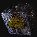
Addendum:
I've been asked about indicator lights - The Atari SX2600 does feature them - They are visible through the vent. Blue for power, Green for networking, and Orange for drive activity. I felt that adding them prominently would take away from the Atari's retro look, however, allowing them to light up the innards beneath the vent provided a visually appealing compromise.

Participated in the
UP! Contest

Participated in the
Game.Life 3 Contest


