

Introduction: Attiny25/45/85 PWM Generator and Servo Tester! Updated Code!


Hello, in this project I want to show you how to build a PWM generator with a Attiny processor. It is very easy to build and a nice project for starters as also for professionals. You will need some electronic knowledge and some knowledge about Arduino. It wont be to hard, because i already wrote a code for the Attiny, which you can use.
This PWM generator also works as servotester, it supports all kinds of servos, which dont need more then 5V
Features:
Operating voltage: 5V
Max PWM current: 1 A
PWM frequency (by now) : 500HZ , I am trying to make that changeable, if you know how, let me know :)
High effency
small size
small prize ;)
...
So lets get started!
Step 1: Material and Tools

The materials will cost less then 4$, also you need a Attiny programmer, i used an Arduino Uno!
Materials:
2 Resistors (450 OHM)
1 Resistor (1 kOHM)
1 BC548 NPN Transistor (or equal)
1 BC516 PNP Transistor (or equal)
some Jumpers
1 Potentiometer (10 kOHM or higher)
serval kinds of terminals (picture 1)
some unisolated wire
1 eight pin IC holder
1 Attiny (25/45/85) I used the Attiny45
some PCB
solder
Tools:
soldering iron
a cutter knife
a pincer
a attiny programmer (Arduino Uno)
a breadbaord
...
Step 2: PCB Layout


Here is the PCB layout i made, beacuse of the less parts it is super simple and easy to build!
The PWM output will be on pin 2 of the Attiny and the analog input will be on pin 4. The BC558 is used as Inverter and as a first amplifier.
After that the BC516 is used to get the current to a maximum rating of 1A, what is actual very good and can drive a pc fan or a dc Motor!!!!
note: the PWM signal is only against 0V not against 5V!
!!! take care dont wire the Transistors wrong, it can cause a shortcircuit!!!
Step 3: PCB Layout #2


Now there is a special about this PWM generator. It has the ability to drive servos, the problem is that different manufacturer sue different pin connections for their servos. That makes problems, when you want to test serval kinds of servos, so i Made a connector system which allows you to change the output pins of the PWM generator!
In picture 1 you can see the system, it has 3 jumper pads, one for the PWM signal, one for 5V (+) and one for 0V (-).
As we change the Jumpers ( picture 2 ) we can change the ouput of the Servo connector on the right side.
!!! NEVER have some Jumpers in a row, it will cause a short circuit and can destroy your PWM generator!!!
In picture 2 the jumpers are correctly plugged!
Step 4: Assemble It!

My PCB looks now like this, I added a few sticker, terminals and a small potentiometer, to make it look nice.
Its your choice how it will look like :)
Step 5: The Software!
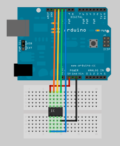
now its time to program the Attiny25/45/85! for this i use a Arduino Uno with a AttinyShield, but you dont need a shield! You can also do that on a Breadboard.
A smal how to:
1: Add the Attiny core to your Arduino software ( http://code.google.com/p/arduino-tiny/ )
2: Wire your Attiny and Arduino like in the Picture 1
3: open your Arduino program
4: go to File>Examples>ArduinoISP
5: Upload it
6: open a new window
7: go to Tools>Board>Attiny45(internal 8 MHZ), click on it
8: now open your code ( code for the project in the next step)
9: Upload it.......wait.....wait.....
10: Error : avrdude: please define PAGEL and BS2 signals in the.....
is okay
11: now your Attiny is programmed! (yay)
Not working?
Check out a full Instructable about it by @randofo its awesome and helped me alot
https://www.instructables.com/id/Program-an-ATtiny-with-Arduino/
Step 6: The Code

Now its time to program the Attiny!
I wrote a code for this project, its made for the Attiny. By now it only supports 500HZ PWM, but i will update it as soon as i can.
My goal is 50HZ, beacuse 50 HZ are needed for a servo.
You can get my code from Git Hub:
https://github.com/Jana-Marie/Attiny-PWM-generat...
Just upload it, as described in step 5, plug your arduino in the PCB and it should work.
The is also a code aviable for the Arduino, dont change them, otherwise it wont work.
Okay, here is a fixed code for servo testing only, it isnt a PWM signal, but it controlls servos!
https://github.com/Jana-Marie/Attiny-PWM-generato...
And also here is a 15 HZ version of the PWM signal!
Step 7: Testing
Finally, your own personal PWM generator using a Attiny25/45/85 is ready for testing! :)
First plug your 5V power source in, it is recommended to use one with a current monitor, because if the current go straight up to more then a few Ampere, you made a mistake (troubleshooting in the next step).
Mine uses a current of 10-20mA
I used an old oscilloscope, but you can also build your own one!
Just check out my other Instructable, How to build a Oscilloscope!!
https://www.instructables.com/id/USB-Oscilloscope-with-Signal-generator/
Important: never place jumpers in the same row!!
Video of the Output signal!!
Step 8: Troubleshooting
Current goes to high:
shortcircuit on the PCB
Built around transistors fals
Built around IC fals
...
No PWM at the output:
make sure you measure against 0V not against 5V
check connections on the board ( maybe something not soldered)
IC not correctly plugged in
Oscilloscope right set?
PCB catches fire
... -.-
Step 9: Ideas!

Idea:
Instead of a potentiometer you can add a heat-dependent resistance and instead of a servo you can add a computer fan to control the speed of you pc fan.
Its just an idea, to add sensors instead of a potentiometer...
Step 10: Finishing
congratulations!
You made your own PWM generator, yes that is your own merit!!!
Also thank you for reading, check out my other projects, and feel free to vote for me in a contest! :)
Jana

Participated in the
Arduino Contest

Participated in the
Gadget Hacking and Accessories Contest

Participated in the
Sensors Contest

Participated in the
Full Spectrum Laser Contest


