

Introduction: Attiny25/45/85 Police Light, With Arduino!


Hello, in this project I want to show you how to build a multi functional Police Light with a Attiny25/45/85 .
It will have serval animations , which can be changed with a button on the circuit board, it has 2 channels, which can be controlled with PWM. That allows us to add serval animations or police light flashing sequences. The maximum rated current per channel is 500mA, that allowes us to control high power LED´s, LED stripes or old Light Bulbs!
Why did i build this?
Well, my motivation was a colleague of mine is a huge fan of very old toy cars, so he asked me if i can repair a broken police light of one of this cars. As it was a american car so a astable multivibrator wasnt a possibility. That is why i used a Attiny to controll it, that allows us to add serval animations!
Features:
Voltage: 5V
Current(stand by): less then 10mA
Serval animations
2 Channels
Both output channels have PWM
Output Current per channel: 500mA
On/Off button
Animation change button
Small size
Step 1: Materials and Tools!

It should cost less then 4$
Materials:
2 Buttons (off/on)
2 Resistors ( 1kOHM )
2 Resistors ( 220kOHM )
2 Resistors ( 450OHM )
2 Diodes ( 1N4007 or Equal )
a Attiny 25/45/85
Some Terminals with screws
a 8 pin IC holder
2 BC548 ( or Equal )
unisolated wire
some solder
a circuit board
For testing:
2 LED´s
Tools:
soldering iron
a forceps
a cutter
Attiny programming:
A attiny programmer
or
a arduino
a breadboard
some wires
a capacitor
or
a arduino
a attiny programming shield
Software:
Arduino ( www.arduino.cc )
You can order the required items on http://de.farnell.com/ , also there you can get more informations about the Arduino board and the Attiny.
Step 2: Circuit Board Layout

Here is my circuit board layout, it is simple and easy fit on a a small circuit board. It also should be easy to assemble.
The 2 output channels will be on the pins 0 & 1 , this are PWM outputs. The pins 3 & 4 will be input pins for the Buttons
Importand, dont wire the Transistors wrong, it can destroy them!
In the circuit plan i made a mistake, the diodes have to go to GND (0V) not to 5V!!!
Step 3: Circuit Board Layout #2


Assembled mine looks like this. There is nothing much to say, its your choice how you like it to look like.
For a single LED we wouldnt need the transistors, but we may want to add more then one LED or we want to add Light bulbs, so the transistors will switch a higher current.
Also you amy want to add stickers, to mark the polarity of the in and outputs and to to add a small description of what it is. :)
Step 4: Software

Now its time to program the Attiny.
I uploaded the code to Git Hub, from there you can get it:
https://github.com/Jana-MarieAttiny-Police-Light/tree/master
It is written by myelf and should work without problems.
There are two versions of the code:
V.1
This version is made to create own animations, it is easier to understand and animations can be changed easy!
But it has s slower menu, buttonchanges may be noticed after a few secconds...
V.2
This one is not made to change the animations, it has german and american police light animations included.
This one has a faster menu, buttonchanges should be noticed within a seccond
If you only want Police Lights you should use V.2!
Step 5: Program It!
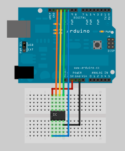

Now its time to program the Attiny25/45/85! for this i use a Arduino Uno with a AttinyShield, but you dont need a shield! You can also do that on a Breadboard.
A smal how to:
1: Add the Attiny core to your Arduino software ( http://code.google.com/p/arduino-tiny/ )
2: Wire your Attiny and Arduino like in the Picture 1
3: open your Arduino program
4: go to File>Examples>ArduinoISP
5: Upload it
6: open a new window
7: go to Tools>Board>Attiny45(internal 8 MHZ), click on it
8: now open your code ( code for the project in the next step)
9: Upload it.......wait.....wait.....
10: Error : avrdude: please define PAGEL and BS2 signals in the.....
is okay
11: now your Attiny is programmed! (yay)
Not working?
Check out a full Instructable about it by @randofo its awesome and helped me alot
https://www.instructables.com/id/Program-an-ATtiny-with-Arduino/
Step 6: Finishing
Now its time to finish this project, plug you attiny into the circuit.
First plug your 5V power source in, it is recommended to use one with a current monitor, because if the current go staright up to more then a few Ampere, you made a mistake (troubleshooting in the enxt step).
controls:
The first button is to turn it on and off, press it to turn it on. To turn it off, press and hold it a few secconds.
When it is turned on press the seccond button to change the animation. With the code V.1 you have to press it a few secconds.
Both LED´s should light up if there is a buttonchange.
Demo:
Step 7: Troubleshooting

Troubleshooting:
Current goes to high:
shortcircuit on the PCB
Built around transistors fals
Built around IC fals
...
No signal at the outputs:
Built around transistors fals
Attiny broken
problem with the power source
Step 8: Ideas:

A idea is to drive 12V leds with it, just use this circuit layout...
Step 9: Thank You for Reading
congratulations!
You made your own police light, yes that is your own merit!!!
Also thank you for reading, check out my other projects, and feel free to vote for me in a contest! :)
Jana

Participated in the
Gadget Hacking and Accessories Contest

Participated in the
Green Electronics Challenge

Participated in the
Full Spectrum Laser Contest

Participated in the
Arduino Contest


