

Introduction: Autodesk Inventor Tutorial


Hello! This instructable is on how to use the most basic functions in Autodesk Inventor. While the version I use (2013) is one year behind, all of the functions work and basically look the same. In this tutorial I will go through sketching, modification and how to export your design. I will be entering the Teach IT! contest, so please vote for me! haha! Well, onto the fun...
You can get free educational trials or by the software at autodesk.com
As a background Autodesk Inventor is a 3d cad software that you can use for design, Instructables is sponsored by Autodesk.
Step 1: Opening a Project
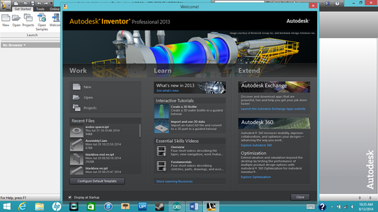

When opening Autodesk Inventor you will see a popup> This is really just asking what you want to do, to open a new project click OPEN.
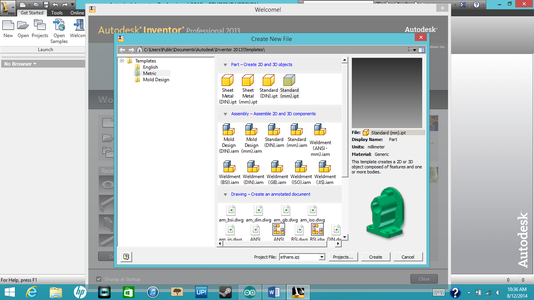
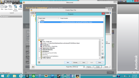
After you click OPEN you will see what is on the second picture. it is always best to open everything you do into a project file. on the bottom left click PROJECTS. On the top you will see a selection that has a list of all previously created projects, if you haven't created one yet click NEW at the bottom. click on NEW SINGLE USER PROJECT than NEXT. On the next screen you can put in your project name and which folder it will be in. After you have done that click FINNISH. Now that you have selected a project you want to open a part file so select standard millimeters or inches and than hit CREATE.
Step 2: Opening a Sketck and Drawing Lines/ Circles


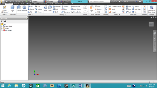
When you are designing you will usually always start off with a 2d sketch. So to start off with a sketch click CREATE 2D SKETCH. You will see like a matrix of each plane (x, y, z). I use the y, x plane, so click on the top-left corner. Now we are in the Sketch view. You don't always have to start sketching this way though, if you have a 3d object already you can start a 2d sketch on the side of it! We will start on the left side of the tool bar and work our way right. So now to start off with a line. Its really easy, you select LINE and you can click on any part of the screen. When you click you have the option of choosing the distance and angle. To switch between the line distance and angle box press tab. When you have made one line you can continue on to make a square, You don't have to select The LINE option every time you want to make a line. If you want to make a shape the line will be selected still and will connect everywhere you click unless if you right-click and press ok, cancel or if you connect the line to a point.
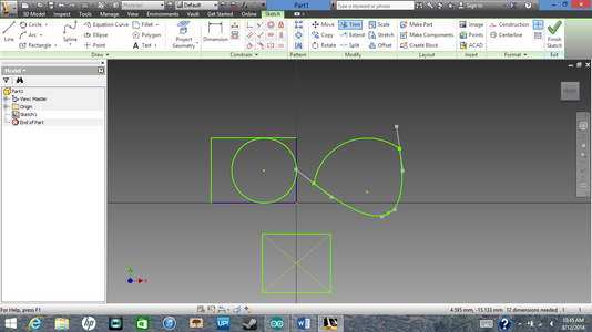
In the picture above I've made a box.
Now onto circles. There is a Circle selection box right next to the LINE selection. You can make two types of circles, from center or tangent, for tangent you select lines that you want the circle to be tangent to. I used the tangent circle and selected the top, bottom and right sides of our box.
Step 3: Arcs


Now for ARCS. Arcs are as you might expect just curves. There are a few ways to make arcs. In the THREE PIONT (shown above), you select two points like a line and select a third point which is where the vertex of the line is going to be. The TANGENT is just like the circle you select lines that you want the arc to be tangent to. And finally CENTER PIONT, this is where you select a point in which you want to center of the arc, you than put the radius, or diameter of the arc down. After that you put down the degrease of angle you want the arc to be.
And that's Arcs!
Step 4: Rectangles


Rectangles are pretty easy so I'll just give you guys a quick touch-up on this. First you select RECTANGLES and how you want to draw the rectangle. I chose TWO-POINT CENTER. Remember you use TAB when you want to switch dimension boxes.
Step 5: Spline


Splines are to me, just wavy lines. you have a few different types of these too. its kind of like ARCS but the second point is the vertex and the third point is the other point.
Step 6: Ellipse's and Points


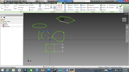
An Ellipse is basically an oval. to make an ellipse you click on ELLIPSE and click a point where you would like one "edge" to be. Than you click where you would like the other "edge" to be. there is no dimensions for this shape but you can dimension it using the DIMENSION button which I will get into later.
Thought they look kind of useless, Points can become your best friend. click on PIONT and fire away! You can use points to create irregular shapes like the hexagon above. during one project "SandWich" (Sandwich cutter I am making and will hopefully post one day) I used points to help me make a saw blade.
Step 7: Fillet/ Chamfer


Fillets are to round edges and chamfers flatten them off like a saw cutting a corner. These are fairly simple to use, after clicking FILLET for example you put in how much you want the edge to chamfer and than select the edge(s) you want to fillet of chamfer.
Step 8: Letters/ Words


Lets say you want to engrave letters or numbers onto one of your 3d images. Find the TEXT button select it and click and drag an areas that you want the letters to be in. While in the text view you can change the font, size, width, spacing and even the rotation of the letters! As an example I typed in the word hi into the hexagon.
Step 9: Dimensioning and Constraints


To dimension an item you select the DIMENSION button and select an edge or two corners to dimension. you than pull the dimension line out click and than type the length you want.
Geometric constraints are really what they say they are, you can make to shapes parallel, the same size, perpendicular, tangent, horizontal or vertical. All you have to do is select the two edges or shapes and BOOM! You just added a constraint.
Step 10: Pattern's

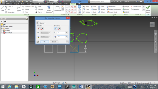

Patterns are great if you are for example designing Legos. Instead of drawing all of the circles and than moving them around you can draw one circle and use the pattern option to quickly and efficiently create more in the places you want them to be. You First start by clicking the RECTANGULAR or CIRCULAR PATTERN button. Than you click on your shape/ sides you want to "pattern." Next you select a side of that shape of another to pick your direction. After that you can change the space between each "patterned" shape and how much you want there to be.
Step 11: Offsets

An offset is a pretty simple function to use. It takes the edge of the shape that you select, and using the same center point it creates an exact replica of the perimeter only larger or smaller which can be dimensioned. To do this select OFFSET and click on the edge of the shape you want to have an offset. than you click on the inside of your shape or the outside (depending if you want the offset to be bigger of smaller) and you can dimension it from there.
Step 12: Finnishing Your Sketck
Now we are done! with sketching for now, later I'm going to go back and touch up on trimming though. To finish your sketch click o FINNISH SKETCH and you will go back into the 3d model view.
Step 13: Extruding and Visualising Your Sketck


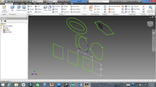
To extrude your sketch or give it volume you select on the EXTRUDE button and click on the shape(s) that you want to extrude. In the extrude box you can change the distance which way the shape will extrude, if its a cut, and how you want to extrude it.
I've extruded the ellipse, but WOAH!!! where did all of the other sketches go?!? They disappeared because Inventor Automatically assumed we were done with our sketch. To show it again you look at the MODEL box on the left side of the screen. Now do you see the name extrude 1? Press on the plus shape on the left, it will drop down to show you what it consists of which is currently one sketch. Right-Click on the sketch and hit visibility. There it is!! Our sketch!!!! now we can finish extruding all of our shapes one at a time or many at a time if we want to extrude them all the same way.
When we are done we can undo the visibility if we want to by pressing on the visibility key again.
Step 14: Rotations


To show rotations I opened a new part, I'll be showing how to make a screw using this so don't close this page or the other page if you are following along .First you make a shape right? Yes. Ok do you see the shape I made? If you were to rotate it in a circle around the left side it would kind of resemble a screw. So in the 3d model window you select on ROTATION and where it says axis you are going to click the flat side of the shape. It should automatically rotate all the way around.
Step 15: Lofts

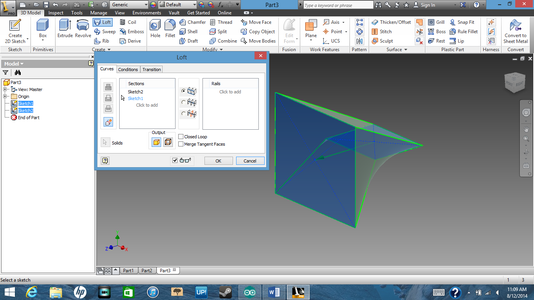
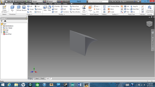
Lofting connects two sketches that are on different axis's or in different positions on the same axis. As an example I made two shapes on different axis's. Than I clicked LOFT and selected the edge of one of the shapes, after that in the loft box hit add selection and thanclick on the other shape
Step 16: Sweeps Trimming and Planes


This is not a broom, this will show you how to make irregular shapes that have the same shape "swept" through them. During the 2d sketch seen above I made the rough outline of a paperclip and than added in some arcs. to get rid of the straight edges I clicked on TRIM and than selected the lines I wanted to trim down.
Now we have finished with the general shape now to make it 3d. To do that we need to add in a plane so we can add the circular shape. So select PLANE and than press on the vertex/ point of the paperclip, than click on the line underneath. If you don't understand what I'm saying please look at the pictures.
When you have that done create a sketch on the plane. Though you cant see the point, the center of the plane is where we are going to make the circle. after I did that, in the model section I changed the visibility of the plane just like we did to the sketch. Now Select on SWEEP and click on the circle and its chosen path (paperclip)
Step 17: Holes


Holes are mush easier than you might think, you create a 3d shapes and sketch some points on them. After that Press HOLE and wow! all of the points are already selected. In the holes menu you can change the width, depth, and the top area (countersink, counterbore, spotface...) so if you wanted to design so you could add screws or bolts they would be flush with the top. Hit enter and your done!
Step 18: Fillet/ Chamfer


these are just like during the 2d sketches. You select either FILLET or CHAMFER select the edges and hit enter. Just like during the 2d design these can change the size but in 3d mode you can fillet and chamfer edges as well as corners.
Step 19: Threading

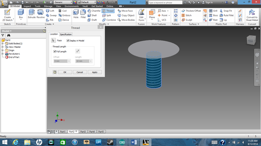

Lets go back to the screw we were making. now we are going to add a thread. to do this select THREAD and select the cylindrical part of the screw. the default threads the whole thing, but you can change that if you want to.
Step 20: Why Not Finnish the Screw? Cuts


Lets just finish the screw! to do that lets make this a flathead screw! I simply sketched a box on the top of the screw. Than while extruding the box I switched the direction and it cut the intersecting area out.
Step 21: Project Geometrey and More Lofts!


Now lets add a cool notch on the top, because why not? I created a sketch on the indented part of the screw and in the middle I added a point.
Next I created a sketch on the top of the screw, but since only one side of the screw was selected I used PROJECT GEOMETERY to project the other side. Now they are both outlined in yellow. Now let us create a circle using the same center point as the other point we just created.
To loft it click the point, Press add selection, and click on the circle. Before you press accept, on the left side of the box select the cut option so it will cut any intersection parts.
Step 22: Appearence


Now we have a grey screw Blah!! We want some color right? On the top select the COLOR WHEEL and the Appearance Browser will show up. Click and drag a box to select the 3d part. in the browser you can search for any color you want (I used aluminum), right click than click on add to selection.
Step 23: Exporting


After you have changed the color you can export the image to a 3d cad format. On the very top left click on the inventor icon and select export. There you can export it as a picture, pdf, cad, etc....
But when exporting as cad make sure to export it as the right cad format eg. STL
Step 24: Finnishing Up

And YEAY!!!! Your done!! If you've read the whole thing thanks very much and happy inventing!!

Participated in the
Teach It! Contest Sponsored by Dremel


