

Introduction: Automatic Window Curtains


Isnt' it a pain to have to actually get up off of the couch to close the curtains? Well I thought so, which led to this project, wireless, automatic curtains that can be controlled over bluetooth and can be set to open/close at a certain time or light level. Documented below is how I went about doing this. I hope you enjoy!
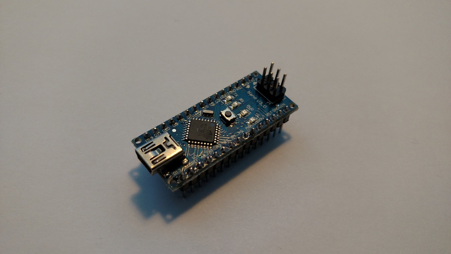
Step 1: Electronics
I like to start all of my project with the electrical part. This is my area of knowledge so I know that I can usually get it done pretty quick. Then the rest of time I can spend on the mechanical parts, with help from friends. Below is what we need to get started for the electronics of this project.
Step 2: Materials Used


Step 3: Required Tools


I use a mini vise to help me hold the PCB while I solder, these are very handy to have around for any project. I prefer using a brass sponge for cleaning my soldering iron tip over a damp kitchen sponge. The brass ones seem to just work better for me and also last a lot longer, as they are not very prone to heat damage. The watch maker glasses are great for inspecting solder joints. Throughout this project I had a couple of minor shorts caused from the way I decided to assemble this project. these things can be pretty helpful at finding small stands shorting pins. They would also be great for SMD assembly!
Step 4: Layout Components

Before you get to soldering components down, you want to lay them out and make sure that they will fit, of course, if you are using a custom PCB this isn't something that would really be done. I wanted my finished item to have a pretty small footprint and I think I have accomplished that pretty well without a custom PCB.
I decided to put my stepper driver on sideways because it wouldn't really fit the other way. Since the pads on this PCB are not connected, this was not a problem. Once I started soldering, I ended up flipping the stepper driver to the opposite side of the board, as shown in later steps. With only three components it wasn't too difficult to decide where to put things. Regardless of where, the same amount of wiring would be needed.
Step 5: Solder Down Components and Wire


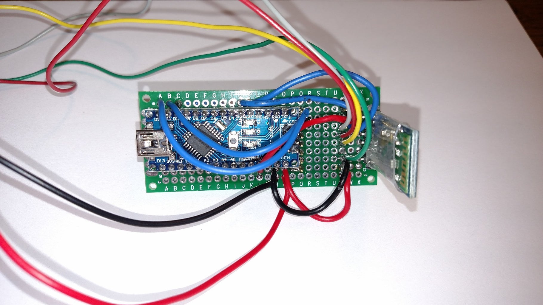
Once I had the components where I wanted them, I stuck the PCB in the vise and got to soldering. Once the main components were in place it was time to start wiring them all together. I intentionally didn't cut the long leads of the components so that I could use them to solder to. On the wires that I actually put through a hole, I created a solder bridge between it and whatever pin it was being connected to.
Here are the connections that I made...
Arduino D2 -> Bluetooth RX
Arduino D3 -> Bluetooth TX
Arduino D10 -> stepper driver ENABLE pin
Arduino D11 -> stepper driver STEP pin
Arduino D12 -> stepper driver DIRECTION pin
Power Supply V+ -> Arduino Vin -> stepper driver VMOT pin
Power Supply V- -> Arduino GND -> stepper driver GND pins -> bluetooth GND
Arduino +5V -> stepper driver VDD -> bluetooth VCC
Stepper driver 1B -> stepper motor GRAY wire
Stepper driver 1A -> stepper motor RED wire
Stepper driver 2A -> stepper motor YELLOW wire
Stepper driver 2B -> stepper motor GREEN wire
NOTE: Not all stepper motors will have the same color pinout!
Step 6: Finished Assembly

My final assembly came out a little messier than I would have liked, but it works! I'm calling this a 'permanent prototype'. If I was not making this to be permanent then I would have likely used headers instead of soldering the Arduino, stepper driver and bluetooth directly to the board.
Step 7: Arduino Code
The code for this is simple. Since the bluetooth module works just like a serial port, I am using the SoftwareSerial library in Arduino to access the signal, allowing me to leave the standard RX/TX pins free so I don't have to disconnect the bluetooth to make program changes. I am using the bluetooth to read a single character that I send to it. Based on the character that it receives, it will either spin the stepper motor clockwise or counter clockwise, opening and closing the curtain. Based on the circumference of the pulleys that I used, I could determine how many revolutions the motor needed to turn. Then take this and determine the correct number of steps that it must turn. I have attached my code. This code has a spot to set the time of a real time clock as well which I will be adding in later.
Attachments

Step 8: Android Control
To be able to control this curtain from your phone I am going to create an Android app with an open/close button, along with a feature that will let you set the time of the RTC as well as set when you want it to open and close. I will probably be using App Inventor, but I may try my hand using Android Studio. In the meantime, I am using Bluetooth spp pro, which is a free download from the Google Play store. Sending an 'o' will open the curtains, sending a 'c' will close them. It's just that simple!
Step 9: Mechanical Assembly - Parts Used
Here is the list of materials that I used for the mechanical portion.
- 2x Stepper motor pulleys- link
- 1x Nema 17 motor mount - had one laying around
- 1x 5mm bolt
- 2x 5mm nuts
- 1x Angle bracket - had one laying around
- Some screws to mount stuff to the wall
- Fishing line or other type of string
Step 10: Tools Used
- Scissors
- Super glue
- Drill
Step 11: Mounting the Motor and Free Pulley to the Window


To mount the motor, I simply held up my mount to the wall, and screwed it in, pretty simple right? I did the same thing for the free pulley, check out the pictures to see how I attached the pulley to the right angle bracket. Since there is about a 6'-7' distance between the motor and the pulley, I wasn't terribly concerned with making sure that the two lined up perfectly. I just eyeballed it.
Step 12: Connecting the Fishing Line


Connecting the fishing line was the hardest part of this project. I started by using a high strength, low stretch type of line but realized that have no play was not going to be a good idea. I switched to standard fishing line that can stretch pretty easily. I put one wrap around the idler pulley and pulled the other end to the pulley on the stepper motor. I could then tie the two ends of the line together to make a loop. I then wrapped this loop multiple times around the stepper motor pulley, until the line was tight.
To attach the curtains, I took some binder clips and clipped them to the curtains, after seeing where those clips met the line, I tied them off to opposite sides of the line, so they go in opposite directions.
UPDATE:
I have added a picture/diagram of how I wrapped the fishing line with the binder clips. In the drawing, with the binder clips in the middle, this is the curtains closed. When you spin the motor one direction, the binder clips will go away from each other, opening the curtains. Reverse the motor and they come towards each other, closing the blinds.
Step 13: Future Steps
I plan to make one of these for each window in my apartment. When that happens I will probably custom name the bluetooth modules so I know which is which. I will also make a custom PCB through OSHPark and use connectors for the components. Other minor improvements will probably also occur along the way. As they do, I will be sure to update this Instructable.
I hope that you have enjoyed this and found it helpful! Please ask any and all questions. I am sure that I missed something or didn't explain something fully.

Participated in the
Tech Contest


