

Introduction: Autonomous Control of RC Car Using Arduino

This instructable shows how to modify an inexpensive RC car so it can be controlled by an on-board microcontroller. You can program the controller to make the car do any number of driving patterns and stunts. Once you have the car being controlled from the on-board controller, you can add sensors for light and sound and make the car do things like line following.
Step 1: Gather Materials and Tools

I used the following materials:
-RC Car - el cheapo from Walmart. It cost $6 at my local Walmart.
-Arduino - I used the Duemilanove purchased from Sparkfun, (www.sparkfun.com)
-4 1000 Ohm 1/8 Watt resistors (color code BRN/BLK/RED). The value of the resistors is not critical. Anything within 50% should work.
- 1/16th inch heatshrink tubing to insulate the resistors after they're installed
- 22 AWG solid wire. You'll need five wires, 6 to 8 inches long. I used Black for the Ground and White for the 4 control wires.
- a small amount of solder
- 2 rubber bands
- 9V battery clip that plugs into the Arduino, also available from Sparkfun
Tools you'll need are:
- small (not tiny) Phillips screwdriver
- wire stripper
- soldering iron
- "third hand" to hold resistors while soldering wires to them
- small tip diagonal wire cutters
- desoldering tool or braid
- tweezers or small needle-nose pliers
Step 2: Disassemble the Car


For this step, you will take the car apart. First, clip off the antenna using a strong pair of cutters. Then, remove the four screws that hold the body on the chassis and separate the body from the chassis. Next, remove the two screws that hold the internal electronics cover. Discard this cover.
Step 3: Remove the Antenna


Remove the screw holding the antenna. Cut the antenna wire near the printed circuit board being careful to only cut the black antenna wire. Discard the antenna and antenna wire.
Step 4: Hack Into the Car's Electronics


Unscrew the single screw holding the printed circuit board (PCB) to the chassis. Carefully turn the PCB over and screw it back down temporarily. Now, using small tip wire cutters, carefully clip each lead on the controller chip. Be sure not to cut any other leads or wire on the PCB. Remove and discard the controller chip.
Step 5: Connect the Wires


Flip the PCB back over. Using a solder sucker or solder braid, unsolder and clean out the holes for pins 2,6,7,10 & 11. Be careful not to use too much heat to avoid damaging the PCB. Prepare four resistor/wire assemblies as follows: Solder solid 22 gauge white wire to a 1K Ohm resistor. Make a total of four of these resistor/wire assemblies.
Insert and solder the resistor leads (the ones not connected to the wire) into the holes for pins 6,7,10 & 11. After soldering, slip a piece of shrink tubing over the wire all the way down to the PCB. Shrink the tubing with a match, lighter or tubing shrinker.
Install and solder a solid black wire into the hole for pin 2.
Mark the white wires with stripes so you'll know which wires control the different functions.
1 stripe - Left signal - pin7;
2 stripes - Right signal - pin 6;
3 stripes - Reverse signal - pin 10;
4 stripes - Forward signal - pin 11;
Step 6: Route the Wires and Reassemble the Car


Drill a 3/8" hole in the rear of the car body for a place where the wires will come outside the car. Place the body on top of the chassis while threading the wires through the hole in the trunk. Screw the body and chassis together using the 4 screws previously removed.
Step 7: Attach the Arduino
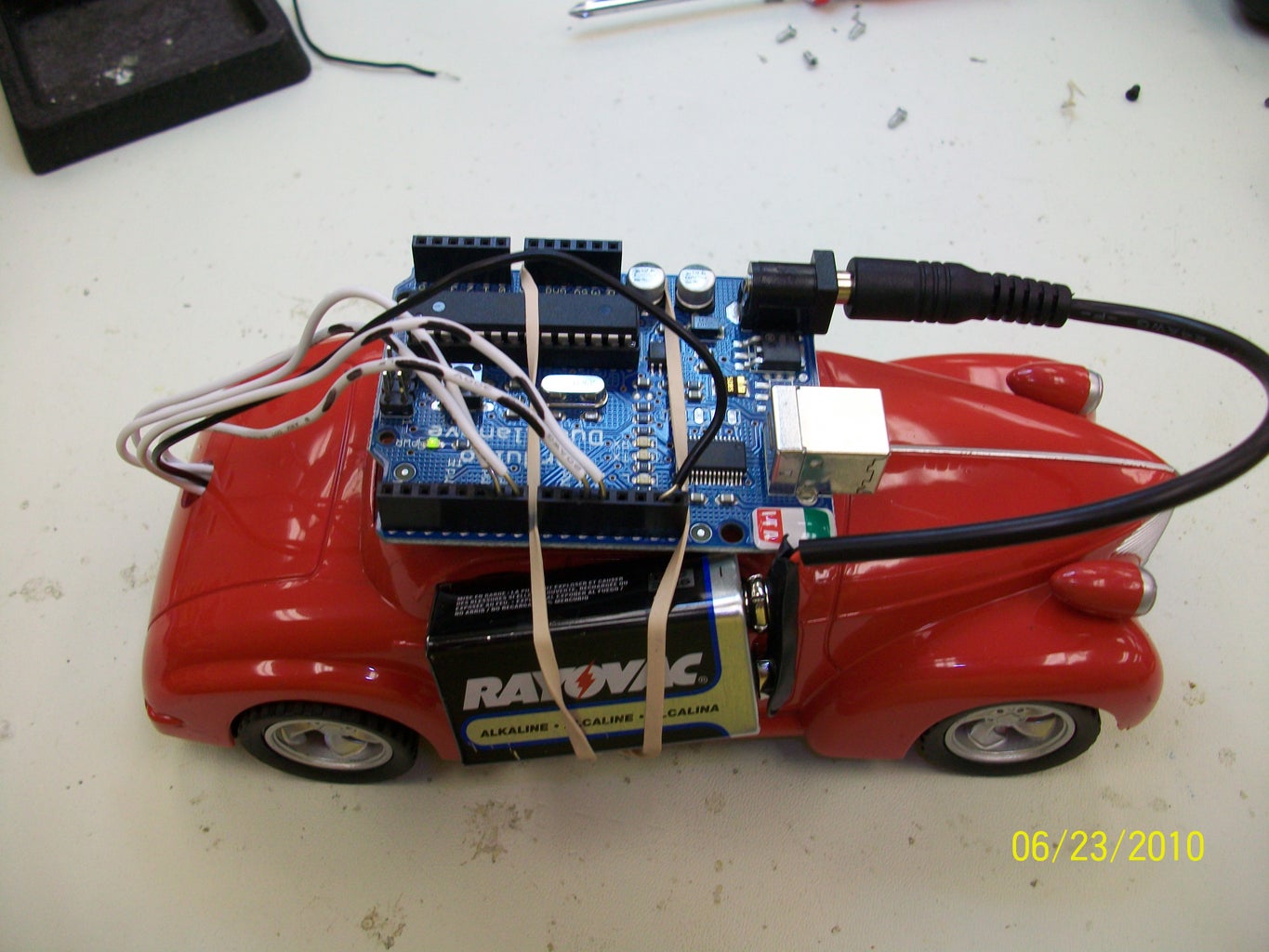

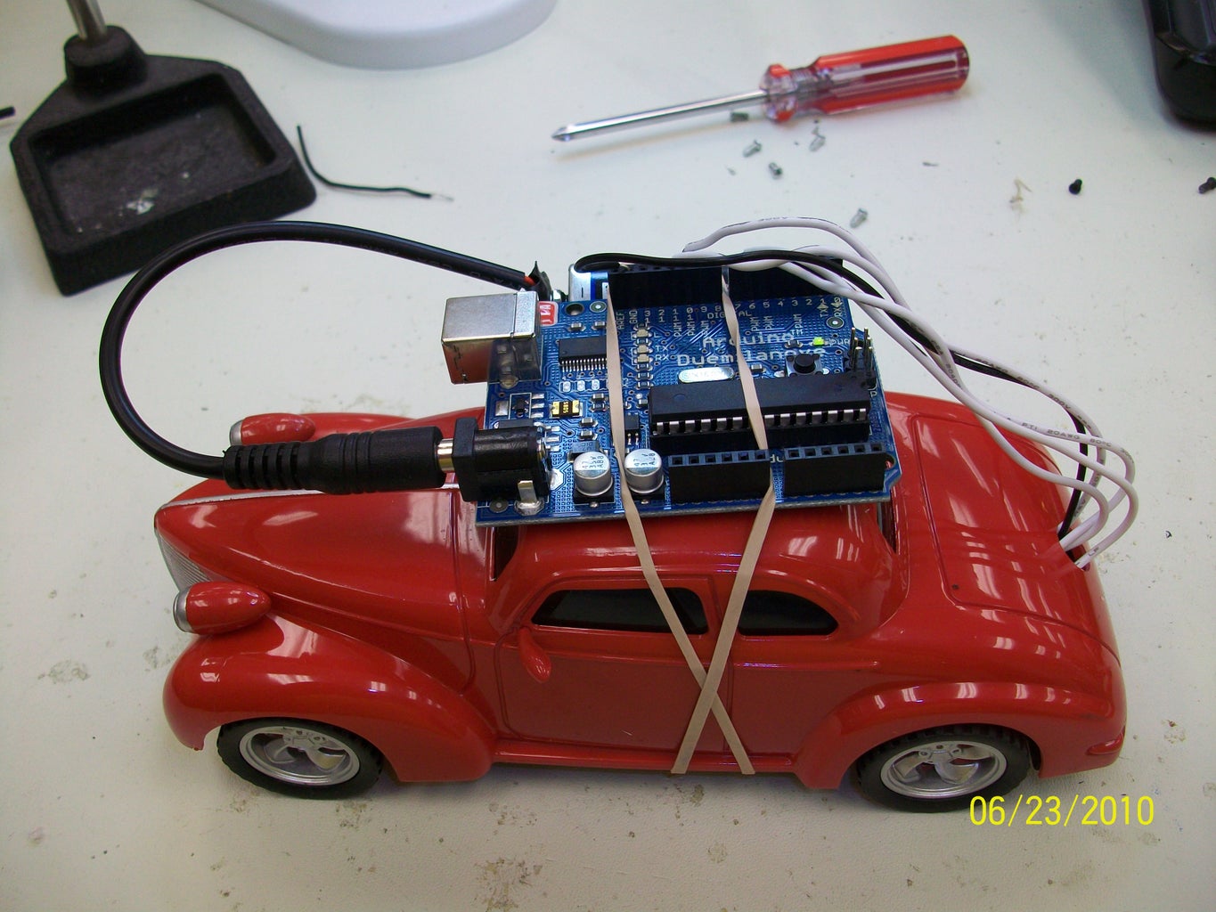
Using rubberbands, attach the Arduino to the roof of the car. Strip the ends of the wires and plug them in to the Arduino pins according to how the program works. Also attach a 9V battery holder and plug it into the Arduino.
Next connect the black wire into the GND pin on the Arduino. Then connect the white wires to the Arduino as determined by your program.
These statements in the Arduino program determine which pins the white wires plug into:
int forward = 12; // forward pin
int reverse = 11; // reverse pin
int left = 10; // left pin
int right = 9; // right pin
Step 8: The FUN! Part

Attached to this Instructable is the Arduino sketch used to make a car go into a continuous figure 8 and a video showing a car doing various tricks.
Some things to remember:
1. Put batteries in the car.
2. Make sure the car is turned OFF.
3. Connect the 9V battery to the Arduino.
4. Verify and Upload the cartest sketch from your computer into the Arduino.
5. Disconnect the programming cable.
6. Turn the car on - it should start running immediately.
If you're new to the Arduino, you can find all the information you need and the programming software at www.arduino.cc
Have Fun!!!


