

Introduction: Autonomous Tank W/ Robotic Arm(Arduino, Bluetooth)
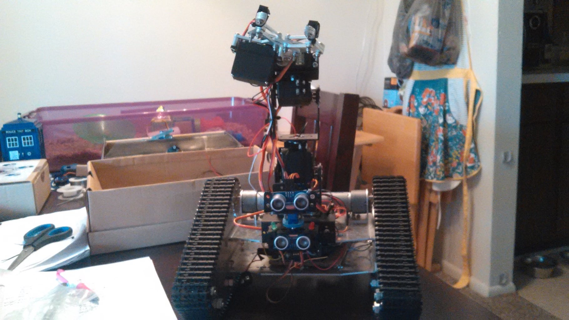
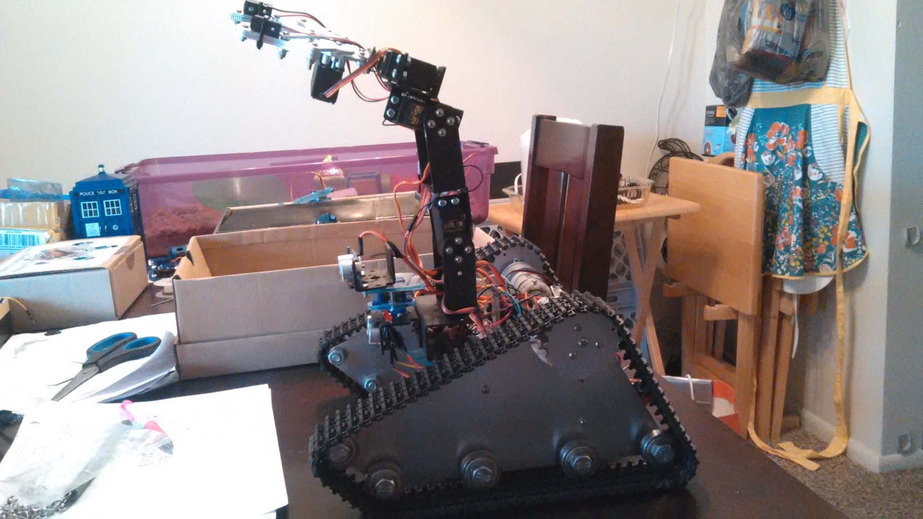


This Instructables will be explaining the process of building an autonomous Arduino tank with an attached robotic arm to be controlled over bluetooth using the Ardudroid Android application.
Direction is controlled via buttons while the servos of the arm are controlled by sliders in the application that are mapped to the minimum and maximum values of the servo. The total cost of this project is approximately $250-300.
The Instructables for the first 2 parts of this build can be found here:
Tank Chassis Assembly:
https://www.instructables.com/id/Robo-TK-100-Tank-C...
Robotic Arm Assembly:
https://www.instructables.com/id/Robotic-Arm-for-Au...
Upgrades coming soon!
Step 1: Parts List


1. Tank Chassis - Smartarduino.com $101.00 http://www.smartarduino.com/view.php?id=94108
A detailed tutorial on how to assemble the chassis can be found here:
https://www.instructables.com/id/Robo-TK-100-Tank-C...
2. Robotic Arm Kit + 4 Servo's - Parts from Ebay/Amazon ~ $80
More information including a tutorial on the Arm build can be found here:
https://www.instructables.com/id/Robotic-Arm-for-Au...
3. Arduino/Clone ~ $12.00 http://www.amazon.com/IEIK-Board-ATmega328P-Cable-...
4. Drok L298N Motor Driver Module ~ $9.00 http://www.amazon.com/DROK-Controller-H-Bridge-Me...
5. Jebtek Bluetooth Slave Module HC-06 ~ $9.00 http://www.amazon.com/JBtek-Wireless-Bluetooth-Tra...
6. Drok Dc/Dc voltage converter 8A ~ $11.00 http://www.amazon.com/gp/product/B00C4QVTNU?psc=1&...
7. Mini Breadboard ~ 5 for $5 http://www.amazon.com/SYB-170-Color-Board-Small-Br...
8. Ultrasonic Sensor ~ 2 for $12 http://www.amazon.com/dp/B00F167T2A/ref=sr_ph_1?m=...
Be Aware that when it comes to ultrasonic sensors you get what you pay for. These will be noisy and require smoothing. More details in the codes section.
9. Adafruit 3.3v Voltage Regulator ~ $3.00 http://www.amazon.com/Adafruit-250mA-Linear-Voltag...
10. Venom 3S Lipo Battery 11.1v ~ $19 http://www.amazon.com/dp/B004UZD4Q8/ref=sr_ph_1?m=...
11. Taxxas Lipo 2S/3S Balancing Charger ~ $18 http://www.amazon.com/Traxxas-2935-Cell-Balance-Ch...
12. Lipo Safe Charging/Storage Bag ~ $8 http://www.amazon.com/Bluecell-Silver-Medium-Batte...
13. Red Rocker Switch - Comes with Tank Chassis Kit
14. Extra Wire 22 AWG ~ $3.00 https://www.sparkfun.com/products/8866
15. Red + Green LED
Step 2: Mount Arm Onto Tank Chasis


If you have been following the Instructables in order then you can skip this step as it is covered in the tutorial for the Arm.
1. You will need a U-bracket w/ attached servo horn and the arm's base.
2. Attach the U-bracket to the top of the base arm with 4 flathead screws/nuts.
3. Bolt the base to the tank frame using 4 flathead screws/nuts. The hole patterns are identical.
Note: This arm was always meant to be attached to my tank chassis. If you only have the arm kit you would screw the two sides of the base together before attaching the arm to it. Also I did not need a servo to rotate the arm from side to side as It was to be mounted on the tank. If you would like left to right rotation for the arm you will need to buy one more servo and change the frame accordingly.
4. First rotate the servo shaft to its center position.
5. Gently pry the sides of the U-bracket open wide enough to slip the bearing and servo shaft into place.
6. Firmly press sides together and add the servo gear shaft screw to secure the horn to the servo.
Step 3: Setting Up the Motor Driver Module


1. If you want to be able to control the speed of each DC motor through PWM you must remove the jumpers over enableA and enableB on the motor driver module as shown in the picture. These will be attached to a PWM pin on the Arduino later.
2. Create a wiring harness for the EnA/EnB, and IN1/IN2/IN3/IN4 as shown.(I taped together 6 female-to-male jumper wires)
3. Before upgrading to the Lipo battery I used a 4xAA 6-Volt battery pack for testing. Attach the Positive and Negative from the module to the Pos and Neg of battery pack.
4. Connect each of the pins IN1, IN2, IN3, and IN4 to a digital Pin on the Arduino. If planning to use my code be sure to use the Arduino pins specified not ones shown in the picture.
5. Connect the EnableA and EnableB pin of the module to 2 PWM pins of the Arduino. Again for my code use the specified pins not the one's shown in the picture.
6. Connect the GND from the motor driver terminal block to one of the grounds of the Arduino.
7. Snip a bit of wire about 8 inches long for each of the 4 terminal blocks. Strip all the ends.
8. Unscrew the screws on the terminal blocks and insert a wire into each before screwing back down again. These wires will be soldered to the DC motors mounted to the tank chassis in the next step.
Note: The L298N motor driver has a 5-volt output on one of its terminal blocks. This can only be used if the voltage in is above 7-volts. For the 4xAA battery pack used above for testing the Vin will only be 6v therefore the 5v output of the motor driver module should not be used. After upgrading to the 11.1v lipo battery the 5v output can be used to power the sensors and Arduino.
For more detailed information on the L298N motor driver module consult this page:
Step 4: Solder Wire to Terminals of Motors


1. Pull the 4 wires you attached to the motor driver terminal blocks in the previous step through the holes in the tank frame closest to the motors.
2. Heat up the soldering iron, grab some solder, and solder the wires coming from the terminal block to the motors. It doesn't matter which side of the terminal block you choose for positive or negative because you can fix it the code later, but be sure to use the same sides for each of the motors.
3. Use some electrical tape or something more permanent to insulate the terminals and exposed ends of wire.
Step 5: Completing Electronics


This section deals with wiring everything together. As it would be too complicated to try and explain the connections in words I used fritzing to create a breadboard view of the wiring diagram. Be sure to pay close attention to the notes and that you are connecting everything to the correct pins.
1. Mount the mini-breadboard onto the top of the tank in the space between the arm and motors using the adhesive background.
2. If you have the type of bluetooth module with headers like mine you can just plug it straight into the breadboard and wire it that way, otherwise you will have to solder wires to each connection point.
3. The voltage regulator used in the Fritzing diagram is not the exact one I used for this project and, as stated in the note, the pin-outs for the two regulators are not the same. Be sure to use the correct pin-out for the adafruit voltage regulator which can be found here: http://www.adafruit.com/images/product-files/2166/...
4. There were no switch parts in frizzing that were close to the one I used. So, add whatever On/Off switch you decide to use in between the power wire somewhere between battery and Motor Driver Module.
5. Next connect one of the battery connectors that came with your lipo battery to the positive coming from the switch and negative from the motor driver module with tape or solder.
Step 6: Create an Ultrasonic Sensor Mount W/ Spare Parts


If you stare at the spare parts on your desk long enough chances are you will be able to think of a way to mount your ultrasonic sensors. The arm kit includes some useful spare parts, nuts and bolts.
1. Slap together a mount to hold the servo, rotating sensor, and stationary sensor.
2. Make a wiring harness for each of your sensors to keep things neat.
3. Mount the sensors.
4. Attach the sensor mount to the frame using 4 small screws/nuts from the Arm kit.
Step 7: Download Ardudroid App


In order to control the tank for now I have been using the Ardudroid App created by Hazim Bitar. Here is the link to it's location in the Google play store https://play.google.com/store/apps/details?id=com....
Bitar has his own website and many other useful applications for Arduino. Senseuduino is another of his apps that is incredibly useful. It is able to utilize just about every sensor on your android phone, send the data to Arduino, and control the Arduino based on the information gathered. Here is a link to his website:
Step 8: Codes


Finally, here are the codes for both the Obstacle avoidance and Android control over bluetooth modes of operation for the tank. New codes, videos, and updates to the project will be added soon.


