

Introduction: BH1750 Digital Light Sensor


BH1750FVI Is a Digital Light sensor , which is an digital Ambient Light Sensor IC for I2C bus interface. This IC is the most suitable to obtain the ambient light data for adjusting LCD and Keypad backlight power of Mobile phone. It is possible to detect wide range at High resolution.( 1 - 65535 lx ).
this sensor has some advantages such like :
1) Illuminance to Digital Converter
2) Wide range and High resolution. ( 1 - 65535 lx )
3) Low Current by power down function
4) 50Hz / 60Hz Light noise reject-function
5) I2C bus Interface ( f / s Mode Support )
6) No need any external parts
7) It is possible to select 2 type of I2C slave-address.
8) It is possible to detect min. 0.11 lx, max. 100000 lx by using this function.
DataSheet for this sensor will be found here
it's easy to use and connect , so Let's started
We will need :
1) Arduino Board" Uno,Nano,mini .. "
2)BH1750 Breakout .
3)Solderless Jumper
4)CD4050 Hex Buffer IC , Or 510 Ohm resistor *3
5)BreadBoard .
Step 1: Definition of Luminous ,Lumen

illuminance is a measure of how much luminous flux is spread over a given area. One can think of luminous flux (measured in lumens) as a measure of the total "amount" of visible light present, and the illuminance as a measure of the intensity of illumination on a surface
Lumen : The unit for the quantity of light flowing from a source in any one second (the luminous power, or luminous flux) is called the lumen.
In our sensor we will take a reading from it in Lux which is equal to one lumen per square metre:
Lux = 1 Lm/m2 .
Step 2: Datasheet .....inside


The DataSheet for BH1750 has a specification of :
Supply voltage : prefer to use 3.3 V to communicate with , Not 5V TTL Logic
I2C Protocol is used to communicate with Microcontroller , with clock SCL Frequency 400KHz .
Measurement mode: this sensor has 3 Measurement mode :
1) H-resolution with Sensitivity 0.5 lux
2) H-Resolution with Sensitivity 1 lux.
3) L-Resolution with Sensitivity 4 lux.
the datasheet recommended to use H-Resolution Mode due to kind of noise( including in 50Hz / 60Hz
noise ) is rejected. And H-Resolution Mode is 1 l x resolution so that it is suitable for darkness ( less than 10 lx )
the Instruction Set Architect table show all commend you will need to write a code .
Step 3: Connection

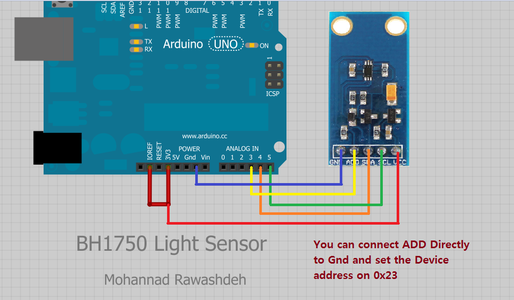


as I mentioned before , the BH1750FVI breakout works with 3.3V , Not with 5V so You can connect this breakout By using :
510 Ohm Resistor , the input voltage on arduino SDA,SCL Pin not greater 3.6V , tested on oscillscope
using CD4050 Hex Buffer 5-3.3 logic converter .
in Newest Arduino Board "Like Arduino Uno R3" Has I/OREF Pin above reset Pin , his pin on the Arduino board provides the voltage reference with which the microcontroller operates. A properly configured shield can read the IOREF pin voltage and select the appropriate power source or enable voltage translators on the outputs for working with the 5V or 3.3V. very nice you can use it .
about ADDR Pin , I prepare a Library " I will talk about in the next step " , You can select the address of your breakout , Even 0x23 , or 0X5C , this action depend on the ADDR Pin status , if connecting to Gnd , the address will be 0x23 , else if ADDR Connecting to Vcc The address will be 0X5C .
Step 4: Arduino Code


I prepared a library for this sensor , You can download it from Here
First Many thanks for Claws , He created a library for BH1750 , You can check it Out .
I prepared a library for it , Tried to solve some issue such like :
1) multi device connecting , You can connect 2 devices of BH1750 WIth different addresses , Depend on ADDR Pin status .
If ADDR = LOW , The address will be 0x23
If ADDR = HIGH, The address will be 0x5C
2)Power down mode , you can put your sensor in power save mode so it's consume 0.01uA .
You can downLoad the library from Github , Unzip the attachment and put it in Libraries folder in arduino Path , then restart the arduino IDE .
You can Open the sketch comes with this library .
First program : Read the Lux value via serial Port .
code :
/*
This is a simple code to test BH1750FVI Light senosr
communicate using I2C Protocol
this library enable 2 slave device address
Main address 0x23
secondary address 0x5C
connect this sensor as following :
VCC >>> 3.3V
SDA >>> A4
SCL >>> A5
addr >> A3
Gnd >>>Gnd
Written By : Mohannad Rawashdeh
*/
// First define the library :
#include <BH1750FVI.h> // Sensor Library
#include <Wire.h> // I2C Library
BH1750FVI LightSensor;
void setup() { // put your setup code here, to run once:
Serial.begin(9600);
LightSensor.begin();
/*
Set the address for this sensor
you can use 2 different address
Device_Address_H "0x5C"
Device_Address_L "0x23"
you must connect Addr pin to A3 .
*/
LightSensor.SetAddress(Device_Address_H);//Address 0x5C
// To adjust the slave on other address , uncomment this line
// lightMeter.SetAddress(Device_Address_L); //Address 0x5C
//-----------------------------------------------
/*
set the Working Mode for this sensor
Select the following Mode:
Continuous_H_resolution_Mode
Continuous_H_resolution_Mode2
Continuous_L_resolution_Mode
OneTime_H_resolution_Mode
OneTime_H_resolution_Mode2
OneTime_L_resolution_Mode
The data sheet recommanded To use Continuous_H_resolution_Mode
*/
LightSensor.SetMode(Continuous_H_resolution_Mode);
Serial.println("Running...");
}
void loop() {
// put your main code here, to run repeatedly:
uint16_t lux = LightSensor.GetLightIntensity();// Get Lux value
Serial.print("Light: ");
Serial.print(lux);
Serial.println(" lux");
delay(1000);
}
Step 5: LED , LCD 1602 and BH1750


code :
/*
This is a simple code to test BH1750FVI Light senosr
communicate using I2C Protocol
this library enable 2 slave device address
Main address 0x23
secondary address 0x5C
connect this sensor as following :
VCC >>> 3.3V
SDA >>> A4
SCL >>> A5
addr >> A3
Gnd >>>Gnd
Written By : Mohannad Rawashdeh
*/
// First define the library :
#include <BH1750FVI.h> // Sensor Library
#include <Wire.h> // I2C Library
uint16_t Light_Intensity=0;
// Call the function
#define LedPin 9 // led connecting to pin D9
BH1750FVI LightSensor;
int SensorValue =0;
void setup() {
// put your setup code here, to run once:
Serial.begin(9600);
// call begin Function so turn the sensor On .
LightSensor.begin();
/*
Set the address for this sensor
you can use 2 different address
Device_Address_H "0x5C"
Device_Address_L "0x23"
you must connect Addr pin to A3 .
*/
LightSensor.SetAddress(Device_Address_H); //Address 0x5C
// To adjust the slave on other address , uncomment this line
// lightMeter.SetAddress(Device_Address_L); //Address 0x5C
//-----------------------------------------------
/*
set the Working Mode for this sensor
Select the following Mode:
Continuous_H_resolution_Mode
Continuous_H_resolution_Mode2
Continuous_L_resolution_Mode
OneTime_H_resolution_Mode
OneTime_H_resolution_Mode2
OneTime_L_resolution_Mode
The data sheet recommanded To use Continuous_H_resolution_Mode
*/
LightSensor.SetMode(Continuous_H_resolution_Mode);
pinMode(9,OUTPUT) // Connect LED With 100ohm resistor
// to pin D9
}
void loop() {
// put your main code here, to run repeatedly:
// call GetLightIntensity() Function , so the sensor read
//the Intensity Value and send it
Light_Intensity=LightSensor.GetLightIntensity();
delay(50);
SensorValue=map(Light_Intensity,0,2000,255,0);
SensorValue=constrain(SensorValue,255,0);
digitalWrite(LedPin,SensorValue);
// ready to another reading .
}
On the library attachment You can find LCD _BH1750 Code , connect a LCD1602 AND BH1750 Together
code :
/*
This is a simple code to test BH1750FVI Light senosr
communicate using I2C Protocol
this library enable 2 slave device address
Main address 0x23
secondary address 0x5C
connect this sensor as following :
VCC >>> 3.3V
SDA >>> A4
SCL >>> A5
addr >> A3
Gnd >>>Gnd
Written By : Mohannad Rawashdeh
*/
// First define the library :
#include <BH1750FVI.h> // Sensor Library
#include <Wire.h> // I2C Library
#include <LiquidCrystal.h>
LiquidCrystal lcd(12, 11, 5, 4, 3, 2);
uint16_t Light_Intensity=0;
// Call the function
BH1750FVI LightSensor;
void setup() {
// put your setup code here, to run once:
Serial.begin(9600);
lcd.begin(16, 2);
// call begin Function so turn the sensor On .
LightSensor.begin();
LightSensor.SetAddress(Device_Address_H); //Address 0x5C
LightSensor.SetMode(Continuous_H_resolution_Mode);
lcd.setCursor(0, 0);
lcd.print("BH1750 Sensor");
lcd.setCursor(1, 1);
lcd.print("Please wait...");
delay(3000);
lcd.clear();
}
void loop() {
// put your main code here, to run repeatedly:
lcd.clear();
lcd.setCursor(0, 0);
lcd.print(" Intensity = ");
lcd.setCursor(5, 1);
Light_Intensity = LightSensor.GetLightIntensity();
lcd.print(Light_Intensity);
lcd.print(" Lux");
delay(2000);
}
This Video For it
Step 6: BH1750FVI Library


the BH1750FVI Library is easy to use .
first , to include the library :
#include <BH1750FVI.h>
give a name for a library to call function through
BH1750FVI LightSensor ;
to begin the library , make sensor ready to use , call :
begin();
force sensor to power Down , call :
Sleep();
to wake up the sensor , call :
Reset();
toSet the address for this sensor ,you can use 2 different address , you must connect Addr pin to A3 .
Device_Address_H "0x5C"
Device_Address_L "0x23"
call :
SetAddress(Device_Address);
set the Working Mode for this sensor , call :
SetMode( Mode);
which mode would be :
Continuous_H_resolution_Mode
Continuous_H_resolution_Mode2
Continuous_L_resolution_Mode
OneTime_H_resolution_Mode
OneTime_H_resolution_Mode2
OneTime_L_resolution_Mode
and finally to get Intensity value call function :
GetLightIntensity();
return value of intensity , 2 Byte .
finally , you can use this sensor to build a simple solar Tracker system or light seeker robot "I will discuss about later "
hope give me a feedback for circuit and library , to make it better .
thank you

Participated in the
Microcontroller Contest


