

Introduction: Bluetooth Controlled LED Wearable With Intel Edison


Have you ever imagined a world where you can change the pattern of a dress with a push of the button? Or one where you are able to change the height of a hem with a swipe of your finger? Technology makes control and customization possible where it wasn't before. Fashion is no exception. The phone has become the most used personal device and while it can be the ultimate tool of distraction, it's also useful as a wireless controller. Color has always been very exciting to me, I can swoon while looking at a shade of lilac and get giddy over a kelly green. Being able to change the color of something that I am wearing has always interested me and always comes to mind as a basic means of control while brainstorming about dynamic wearables.
Using a bluetooth enabled microcontroller and Android phone, this project gives you control over a strips of RGB LEDs. These LEDs can be put anywhere, on a pair of boots, in a jacket or on a bike helmet. I chose to take inspiration from 1980 Sci-Fi movies and Kraftwerk to make two accessories; a laser etched visor and a laser cut necklace. This Instructable will teach you how to use the Edison in tandem with your phone to control an RGB LED wirelessly and how to create two laser cut/etched acrylic accessories.
Step 1: Gather Materials

The materials listed are for both acrylic accessories.
Materials
[1] Intel Edison with mini breakout board
[7" x 10"] stiff black leather (for two battery packs)
[12" x 12"] soft black leather
[14" x 14"] 1/8" thick clear sheet acrylic (necklace)
[12" x 12"] 1/16" thick white poly/acrylic combination
[4] heavy duty snaps
[1] meter analog RGB LED strip (get it with no waterproof casing to keep it low profile)
[1/4 size] perma-proto board
ribbon cable
male and female headers
electrical tape
Acrylic Cement
5-Minute Epoxy
Barge contact cement
Tools
heavy duty snap setter
leather hole punch or awl
scissors
heavy duty hand needle
leather hand needle
leather matching thread
soldering iron and tools
laser cutter (to make included accessory designs)
Step 2: Setup Edison

If this is your first time using the Edison, it will need to be setup before being able to develop projects with it. Follow Intel's tutorial on their website, it will walk you through the basics, which include:
- Learning how to connect and communicate with the board through serial and wirelessly
- Enabling WiFi
- What software to download and how to install it
- Uploading first Blink program using Arduino, JavaScript, Python or C++
The language we will be using in this Instructable is Python, I use Windows OS, but you can use Mac just as well, I will do my best to mention any differences, if applicable. We will upload the Python scripts using a FTP client, such as WinSCP for Windows or Filezilla for Mac, so you do not need to download Intel's XDK or any other of it's development environments. Outside of this 'ible, I encourage you to explore using these later.
Head over to Intel's website and go through the "Getting Started" steps.
Step 3: Download Bluetooth SPP Pro

Download and install the Android app, Bluetooth SPP Pro from here or directly on to the phone from the Play store.
Step 4: Serial Port Profile
This is done through SPP (Serial Port Profile). This enables two devices to create a virtual serial port connection so they can communicate with each other. For this connection to work, there needs to be a file modified on the Edison's directory. This is gone over in Edison's Bluetooth Guide, provided by Intel. I have attached this guide and recommend reading the Basic Bluetooth Operation, Scanning and Connecting Devices and Serial Port Profile sections. My steps here are condensed versions of these.
Using a FTP client, like Filezilla and WinSCP, find the file /etc/dbus-1/system.d/bluetooth.conf. If you are in the root directory go back two directories to find /etc/. If bluetooth.conf does not include this line:
<allow send_interface="org.bluez.Profile1"/>
Add it and save the file. The virtual serial port is created by a python script running in the background, this script is provided by Intel and called SPP-loopback.py. For this project, I added additional python code that says if the data coming through the virtual port equals a "1", display red, if it equals a "2", display green, etc. The colors are displayed on the RGB LED by sending different levels of voltages to each of the pins hooked up to each red, green and blue leg of LED, mixing different brightness levels to create colors.
Attached to this step is the original script, SPP-loopback.py, that will send data from one bluetooth device to another. The script called colors.py is the final script for this project that includes the RGB LED functionality.
Upload colors.py to the root directory of the Edison.


Step 5: Enable Bluetooth on Edison and Run Script

Open up puTTY and login in to the Edison.
Before doing anything bluetooth, the bluetooth chip needs to be unblocked. This needs to be run every time the Edison is power cycled.
rfkill unblock bluetooth
Once the rfkill command unblocks bluetooth, the python script needs to be executed to run in the background. The ampersandmeans that it will run in the background.
python colors.py &
Step 6: Scan and Connect to Phone


There is a command line utility that we will use to make our device discoverable, pair and connect our devices.
bluetoothctl
To see all the available commands in the bluetoothctl utility. This isn't a necessary step, but can be helpful to see what else can be done while in the utility.
help
Once in the bluetoothctl utility these are the commands that will connect the edison to the Android phone. Make sure that the phone is discoverable, which can be done in the phone's Settings.
agent KeyboardDisplay
default-agent
scan on
The scan on command displays the MAC addresses of all the bluetooth discoverable devices that are in the area. Wait for the phone to pop up, once it does, copy the address. It will look something like AA:66:00:11:BB:77. Now you can pair and tell the edison to trust the phone so you do not have to go through an additional level of confirmation.
pair AA:66:00:11:BB:77
trust AA:66:00:11:BB:77
scan off
The edison is now paired with your phone. Now, it's time to connect.
connect AA:66:00:11:BB:77
While pairing or connecting, here are some common errors and how to fix them:
Failed to pair: org.bluez.Error.ConnectionAttemptFailed
The phone is still paired with a device. If you are going through the process again with the same device, you may also need to go in to your phone's settings -> bluetooth and forget the device there as well. Use this command to remove the device from the Edison.
remove <MAC address of previous device>
If you get an error telling you that the device is unavailable, wait a few minutes, or exit out of puTTY or terminal and establish a new serial or SSH connection and go through the command list again.
Device is unavailable<br>
Sometimes it takes a couple times to get used to paring two devices, when you attempt to, there will be window that pops up on the phone asking to verify a passkey. If you haven't trusted the MAC address of the device that you are pairing with the Edison, it will ask you to verify on that side too. Usually you verify on the phone side first, then the Edison. If you accidentally get the order wrong, wait too long or forget a command, this error will happen. No need to worry, just go through the commands again.
Failed to pair: org.bluez.Error.ConnectionAttemptFailed
Step 7: Connect and Create SPP With App


Now it should say that you are connected to the Edison in your phone's bluetooth settings. Next, the Edison needs to be connected to the SPP app.
Pick up the phone and open the Bluetooth SPP app. The app will automatically start to scan for devices, for the Edison to be seen by the app, use this command.
discoverable on
if the Edison does not pop up the first time, hit rescan. Choose the Edison and hit connect. Once the connection is made, a message will pop up in puTTY on the edison side announcing there is a "new connection".
In the app, three different interfaces will come up to choose from, byte stream, keyboard and command line. Choose command line, type in some characters and push send. The message will show up in puTTY, coming through the virtual port from phone to Edison.
After your board is paired and connected to the phone once, it will stay paired. This means that you can skip the pair and connect commands in puTTY and go straight to this step, making it discoverable to connect through the SPP app.
Step 8: Assign Characters to App Buttons


When in keyboard mode, click the upper right menu and choose to set buttons. In the python script, colors.py, the colors are set to 1 character. This script is written for an LED strip that has common power, if using a power strip with common ground, changes to the values that are sent to the ouput pins need to be made. The board recognizes a range from 0 - 1. For a common power strip, 0 will mean that pin will output the max voltage it can receive (in this case, 9 volts through the logic inverter), so the LED will be at it's brightness. 1 means no voltage, the LED is completely off. You can achieve different levels of brightness by using decimals, high to medium brightness : 0.1 - 0.5, medium to low brightness levels : 0.5 - 0.9.
If the strip is common ground, the logic is flipped, 1 means fully on and 0 means off. This also means that all the decimals in between get flipped. use 0.5 - 0.9 as a way to get medium - high brightness and anything below .5 to get medium - low brightness.
Change the keys in the app to reflect the characters used in the colors.py script.
Red - 1
Green - 2
Blue - 3
Yellow - 4
Pink - 5
Purple - 6
White - 7
Blue green - 8
Green - 9
Orange - 10
Yellow green - 11
Off - any character
After they are set, when pushed, each button will fire off the character assigned to it. This too will print in the puTTY screen, along with the file type, which gets ignored by the script. With this data coming in, you can now trigger what ever you like in the python code.
Play around with the pin values to make your own colors and change the characters to whatever you like in code, just don't forget to assign them to the buttons in the app.
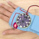
Step 9: Build Circuit


The Edison Mini breakout board can output a maximum of 1.8 volts from it's PWM pins. The analog RGB LED strip needs a maximum of 12 volts, but can operate on 9 volts, which is beneficial for this project because a 9 volt is much smaller than 8 AAA batteries.
To get the correct voltage to the LED strips and still be able to control the pins with the Edison, a logic level converter is needed. The high voltage supply and the strip get hooked up to one side and the low voltage supply and Edison's output pins get hooked up to the other side. Transistors on the board are triggered by the 1.8v coming from the pins, letting the 9 volts to flow to the strip. These are super nifty and very useful, I recommend stocking up a few.
Use angle cutters to cut the width and length down of a perf board. Leave enough room for the inverter to be soldered over the middle so all the pins can be accessed and soldered to. After all the connections are soldered, use electrical tape to cover up all showing metal so no shorts occurred when stacked to fit in the battery pack.
After this circuit is hooked up, you have a bluetooth controlled LED strip to do with whatever you want. If you would like to build it one of the accessories, continue on.
Step 10: Laser Acrylic


Necklace
Before the pieces get cut, print out the PDF, this is used to label all of the pieces before they get taken out of the cutter. Leave the protective covering on the acrylic.
Open the file in Illustrator, double check the stroke, making sure it's .001 pt. Place the 1/8" clear acrylic in the cutter and follow the instructions specific to your machine and setup to cut the file.
Before taking the pieces out of the cutter, use a sharpie and the printed PDF to identify the pieces and label them with the numbers on the plastic film coverings. After labeling, take all the pieces out carefully, acrylic can be brittle and chip.
On a 120 Watt Epilog machine, use these settings.
Vector Cutting
30 speed
80 power
5000 frequency
Visor
The visor file is etched, then cut out of 1/8" clear acrylic.
The visor arms can be made in two ways, they can be cut from the 1/16" plastic and a softer leather, then attached to create solid enough arms that will hold up the visor. Or, they can be cut from stiff leather if it is stiff enough to hold the visor up on it's own. The next step gives settings to cut 1/8" stiff leather.
On a 120 Watt Epilog machine, use these settings.
Etching
25 speed
75 power
Vector Cutting
30 speed
80 power
5000 frequency
Step 11: Cut Leather

You can use a laser cutter to cut the battery pack out of stiff leather, or sharp x-actor. For softer leather, use a blade, it's easy to cut and it won't give off a burnt smell. Cut the amounts below out of the leather indicated.
Necklace
1 x Battery Pack (stiff)
2 x Collar (soft)
1 x Strip (soft)
2 x Fastener Strip A
2 x Fastener Strip B
Visor
2 x Strip (soft)
2 x Arms (soft with plastic backing, or stiff)
Step 12: Solder LED Strips

For both projects, solder a 4 conductor width of ribbon cable to the LED strip with female headers at the end so it can be detached easily.
Necklace
Make the length of wire just long enough to fit through the battery pack and connect to the board.
Visor
Cut the length long enough to end in a shirt or pant pocket, where the board and battery can fit. Unlike the necklace, the battery pack does not live on the accessory itself and will need to be placed somewhere like a pocket.
Step 13: Put Together Necklace - Acrylic


The necklace is comprised of two curved piece that have teeth, like a comb. The smaller pieces of acrylic have two openings that slide into the openings between these teeth on each piece. The two pieces are placed parallel to each other, but starting with one will make putting it together easier in the end.
Grab one curved piece and pieces 4 - 14. Take off the protective film, while keeping the number in mind, and slide the piece into it's matching slot. Do this with all 11 pieces.
Take the second curved piece, matching it with the first, slide it into place.
Ok, now for the trickiest part, inserting #3 and #16. These pieces lock in with the back and the front of the necklace. Twist the piece so it can be lined with the slots in the front and positioned to be pushed back into the ones behind. Take you time, acrylic is brittle and can break when pushed too hard.
Slide the last 1, 2 and 17, 18 in place. Lastly, slide 4 and 15 in place, creating the end cap pieces.
Step 14: Put Together Necklace - Leather and LEDs


Use Barge to glue the fastener strips together, wrong sides together. This makes them more suitable to handle snaps and the pulling that is needed from taking the necklace on and off. If you feel that they still may be too soft, add a third piece in between or some fusible interfacing to toughen it up.
Sew the strip piece to the edge of the inside curve on each of the collar pieces with a 1/8" seam allowance, sew the seam on the outside. Do this using a teflon foot on a regular sewing machine, a walking foot machine or grab a hand needle and sew using a back stitch and leather needle.
Battery Pack
Double thread a needle and fold two edges of the battery pack together so the holes line up. Thread the needle through a hole close to the corner and tie a knot using the end and the length of the thread. Once secured with a knot, continue to sew through the holes using a whip stitch, end with a knot.
Fastener
Take the longest faster strip and thread it through the slits on the top of the battery pack. Next, slide it through the necklace behind one of the end pieces. Take the end and thread it through the bottom of the pack. The pack is now attached by locking a loop of the strip behind the acrylic end piece. Thread the shorter fastener strip the same way, behind the other end piece. Attach the female side of a snap to the ends of the short strip and the male sides to the long strip. This is the way that the necklace is fastened, so check to see if the strips are long enough for your neck and easily snap on and off. The necklace is designed to be snug, the size can easily be altered by using the scale function in Illustrator.
LED Strip
Apply glue to the back of the strip and to the leather strip and attach. Cut a 7/8" width strip of thin acrylic and epoxy on top of the LED strip.
Place the strip with the leather inside the plastic necklace. Apply acrylic cement where the strip and necklace touch, this happens on the sides and it touches the top edges of acrylic pieces in the front. Hold in place until it dries, which is within a couple minutes or less.
Step 15: Mold Acrylic for Visor

Following this 'ible, I learned that you can easily form acrylic in your home over. I've read that acrylic will not give off toxic fumes that can be transferred to food cooked in the oven later. However, it can still produce an odor, do this with a window or door open in your kitchen.
In the linked 'ible, felt is used to hold and manipulate the acrylic, unfortunately the felt imprints and sticks to the acrylic, creating a fuzzy texture. To protect the clear acrylic, I used the felt very sparingly and did not place the whole acrylic piece on the felt at any time.
Set the oven to 300º F and place some foil on a cookie sheet. When preheated, place the visor piece in, etch side up. Heat for 7 minutes.
Immediately take the piece out and off the cookie by grabbing the foil. Carefully flip the piece over, using the foil, onto a small pan or bowl that is close to the curvature of your head. Use your finger tips to guide the acrylic by touching it's edges. Be careful, it will be hot! Use some felt to protect your fingers, but be careful not to imprint the fuzziness of the felt.
Gravity will do most of the work, relaxing the acrylic over the curve it's placed on. Once a couple minutes have passed and it's cooled a bit, but still malleable, press down the edges to hold the visor close to the curve as it cools completely. It should cool enough to stay in shape in a total of 10 minutes.
Step 16: Put Together Visor


Arms
If attaching two pieces to create an arm, use Barge to glue the plastic and leather together.
Line up the arms with the holes on the side of the acrylic visor. Mix up a little bit of epoxy and use a little bit of it to coat the 4 1/4", size 8 screws. Place them in the top two holes on both sides. Use a little of epoxy if they feel loose. These will be not be secured with nuts on the back because the length would get in the way of the strip. They are more for aesthetics, but if glued in place, will help keep the arms in place. Place the remaining 3/8" long screws in and screw the nuts on the back.
LED Strip
Drop some epoxy between the LEDs on the strip, build up some tall drops, they need to be tall enough to reach past the LEDs to connect with the acrylic. Wait a couple minutes for the epoxy to thicken up a bit. Center the strip at the top of the visor and hold in place until it dries.
Use double-stick tape or 5-minute Epoxy to attach a strip of leather to the top edge of the visor, this will be covering up the LED strip, so make sure that it's lined up correctly, if using epoxy.
Finish by gluing the second leather strip on top of the LED strip to cover it up.
Step 17: Plug in and Connect


Edison setup?
✅
Bluetooth enabled and tested?
✅
Circuit built?
✅
Connect the LED strip to the board and power it by connecting the 9 volt battery to it. Open puTTY or Terminal and SSH in to the Edison.
To recap, let's go over the commands needed from earlier steps to run script and communicate via bluetooth.
Needed only if you have power cycled the Edison since the last time you ran this command.
rfkill unblock bluetooth
Run the python script in the background.
python colors.py &<br>
Go into the bluetoothctl utility.
bluetoothctl
Setup agent.
agent KeyboardDisplay
default-agent
If the phone is not already paired with your Edison (check in Settings --> Bluetooth), scan, pair, trust and connect.
scan on
pair AA:66:00:11:BB:77
trust AA:66:00:11:BB:77
scan off
connect AA:66:00:11:BB:77
Pick up the Android device, open up Bluetooth SPP Pro, it will start scanning for the Edison. To make the Edison discoverable, use this command in bluetoothctl utility.
discoverable on
Connect through the app, go to keyboard mode and hit each button to change the color of the LEDs. You can also type the characters in command mode. Have fun with it and Sci-Fi on!


