

Introduction: Backlit Smart House Numbers


House numbers are usually conservative and quite boring devices. We lacked even a boring house number and some action was needed to change that. Now we recently installed a Giraffe mailbox which should help any visitor to identify our house with ease during the day time. But what about night time?
Obviously we needed an eccentric backlit smart house number that was colorful and fun.
- Backlit so it can be seen in the dark
- Smart because it can detect when to switch itself on and off
- House number since we had none
- Fun because it changes colors every night and has a party mode where it switches colors every 3 seconds for get togethers
Surely nobody will miss our house ever again. Not even when the dark ages start again.
Here is how we did it.
Superbender
Step 1: Tools


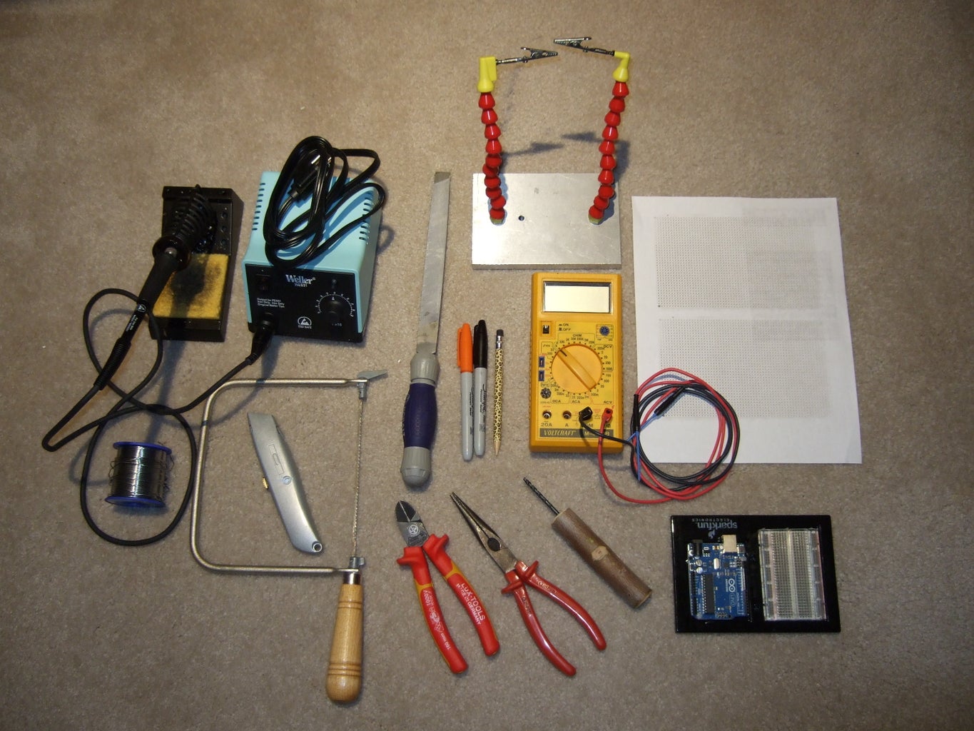
The following tools were used to complete this build:
- Carpenters square
- Pencils
- Folding carpenter's ruler
- Table saw
- Computer
- Projector
- Scroll saw
- Drill press
- Drill bit set for brad pit drills and all purpose drills
- Sandpaper 220 grid
- Paint Brush
- Solder Iron
- Power Supply 9V
- Power Supply 12V
- Arduino Uno Development Board
- Combination square
- Thumbtacks
- Clothespins
- Hammer
- Center Punch
- Small Paint Brush
- Screw Drivers
Step 2: Materials


For the house numbers, any links are just examples
- Light paint for backside
- House paint for frontside
- Any color paint for marking
- Waterproof Red/Green/Blue LED strip, only ~3-4 sections needed per Number, total of 15 used
- Wax paper
- Solder
- Electronics components (see details in Step 10)
- Clear Caulk
- Old telephone cable
- Two wire cable
- 1/4" ply wood
- Piece of wall siding
- Scrap wood for standoffs
- Old chocolate box
- Epoxy glue
Step 3: The Numbers


This step describes the fabrication of the custom sized numbers.
- Decide on the mounting location. We decided that the house numbers will be mounted above the garage door and determined the size for them to be 30 cm (that is about 12").
- Pick a font. The"Century Schoolbook L" was our choice because we liked its soft but clear look.
- Cut a section of plywood that is large enough to accommodate your house numbers. Our plywood thickness was 1/4".
- Place your plywood at a wall and project your house number on it in the desired size.
- Trace the numbers carefully with a pencil or pen.
- Cut out the outside of the numbers. We used a scroll saw. but other saws that allow to cut tight turns will work as well.
- Some numbers require inside cutouts. Drill at least one hole into the inside section. I drilled several holes close to, but inside the lines.
- Feed the saw blade into the hole. I needed to remove the top fastener of the scroll saw blade and bent it sidewards a little to feed the blade into the hole without breaking it.
- Cut out the inside and remove the blade again.
- Sand all the edges. I used 220 grit sand paper.
- Paint the numbers with exterior paint. I recommend white paint for the back side to achieve the best reflection of the light. For the front I used the white color as a base and then the accent color of our house which is a reddish brown as the finish.
Step 4: Light Tests


This step describes the testing of the LED lights and the determination of the standoff length.
- Cut the LED strip in short sections at the intended cutting locations. For the strip that I had each section had three LEDs.
- The LED strip was silicon sealed and thus weather resistant. This is obviously useful for prolonged outside use. I used a carpet knife blade to cut into the silicone above the contacts and then pried away the silicone protection.
- Select locations for the standoffs and the short LED strips on the backside of the number. Consider that the standoffs create shadows. The LEDs need to be placed on several sides of the standoffs such that minimum shadows are created. Mark the location.
- Connect the LED strips in series with each other. Don't worry about the cable routing. This is a test for placing the LEDs and standoffs only.
- Fasten the LED strips with tape on the number.
- Cut 8-10 small blocks of scrap wood. I used about 1x2 sizes for my standoffs.
- Flip the number around and place it on the wood blocks. Light it up with a 12V power source. Vary the height of the adjustable standoffs until you get a continuous light distribution. Move the LEDs if needed. Try again until you have a solutions that works.
- I needed four blocks. Total standoff height was 8.5 cm.
- Once you know the length of the standoffs, repeat testing the standoff and LED locations with every number so that you can detect and eliminate any unintentional shading from the standoffs.
Step 5: Standoffs


This step describes the fabrication of the standoffs.
- Cut all the standoffs you need to the length determined in the previous step.
- On half of the standoffs mark the location for the cable hole in a corner of the standoff.
- In these standoff use a drill press and drill a hole that is wide enough to accommodate the cable coming from the LEDs.
- Turn those standoff over to the side and drill into the side to give the cable a side exit to the back of the house number.
- Paint all standoffs in the main color of your house. I used pushpins to be able to paint all sides at the same time.
Step 6: Drill Template


This steps describes how to make a drill template that helps drilling the holes in your house wall or your cover sheet exactly where you need them.
- On a scrap sheet of laminate/wood material carefully determine the spacing of the house numbers.
- Lay the first number down.
- Trace it with a pencil.
- Create the proper spacing ( I used 5 cm between numbers) and mark it with a pencil.
- Repeat with next number until you have all numbers.
- Take a piece of wax paper (usually used for baking) and trace the numbers onto the wax paper.
- Transfer the location of the standoff to the wax paper as well.
- Mark the center of the standoff on the wax paper.
- Remove the number.
- Align the traced number on the wax paper with the traced number on the drill template.
- With a center punch and a hammer, punch the marked drill location through the wax paper into the drilling template.
- Mark an X on the drilling template for easier visibility of the marked spots.
- Align the drill template number and the wax paper.
- Align the standoffs that will carry the cable to the number such that the hole for the cable exit points downward when the number is installed.
- Mark the location on the wax paper. I found that a brush and some paint worked best.
- With a center punch and a hammer, punch the marked drill location through the wax paper into the drilling template.
- Repeat for each number.
- With a drill or drill press drill out the marked holes. The cable holes should have the same diameter than the hole in the standoff. The fastening holes should be clearance holes for the screws you want to use for fastening the numbers.
Step 7: Completing the Numbers


In this step we are completing the electronic assembly and testing of the numbers.
- With reliable glue that will be able to withstand the environments glue the LED strips to the predetermined locations. I used two component epoxy glue from Loctite.
- Identify the wires/cable you like to use. I used leftovers from telephone cables that we pulled off the house when we painted it. Single strand, probably been up for 30 years or so.
- Carefully route cable pieces from LED strip to LED strip and connect them in series with each other. Consider out of which standoff the cable comes and how you can route it most efficiently.
- Secure the cable and protect the solder joints with epoxy glue or silicone.
- Test each color using some test leads and a 12V power source.
- Run the appropriate cable length through the standoff and glue both standoffs onto the number. I still used the epoxy glue for this step.
- Attach the cable to the appropriate LED strip.
- Test it again.
- Fasten it with epoxy and close the hole where it comes out of the standoff with epoxy glue as well.
- Note that one number is special. It has to hold a photocell, or light dependent resistor (LDR).
- Measure the diameter of the LDR.
- Drill a hole in the number that you like to hold it, but make sure that this number is not subject to the light of a street lantern.
- Insulate the legs of the LDR with shrink tubing.
- Glue the LDR into the hole. I covered mine with a light layer of epoxy to make it more water proof, hoping (not knowing) that it won't get fogged up by extended exposure to sun light.
- Solder the connections of the LDR to two additional wires that are fed through the standoff.
- Seal and glue everything in place.
Step 8: The Brains I (Software)


In this step I'll elaborate on the software that I developed for this build. I used the arduino editor and tested using an arduino uno R3, a breadboard and the required parts. Once the hardware and software was successfully tested a strip board was created that used an atmega 328P as the brain. You could call that a DIYduino. The .ino file is available for download in this step as well. The .ino file is now an updated improved version. In the new version the party button can be pressed during the day as well as during the night.
The software is essentially a state machine that consists of 5 states. The flow chart will give you the best overview of how the software works.
State0 = it is daylight:
When the state0 exists it is daylight. The state0 checks permanently if it is dark yet. Once it realizes that it is dark it will change the state from state0 to state1, which means it is dark now.
State1 = select a color:
When state1 is reached, the software picks randomly a color, sets the color, switches the light on and changes the state1 to state2 or state4 depending on if the party button is pressed. The random color is actually three randomly chosen intensity levels, one for each red, green, or blue color in the RGB LED strip. To create each random intensity state the analog input pin0 is read. This pin is connected to a piece of wire. The wire acts as an antenna and is supposed to maximize noise and thus randomness. The value from pin0 is fed into a random seed function and a random value between 0 and 255 is created. This process is repeated for each color and the results are used for the pulse width modulation (PWM) value of each color. The three PWM signals are fed to the LEDs and together give the random color.
State2 = it is dark, no party button pressed:
This is the standard case when its dark. We essentially check if it is light yet. If the answer is yes, we go back to state0. If the answer is no, we go to state3.
State3 = it is dark, no party button pressed:
State3 and state2 build a loop. As long as it remains dark and the party button is not pressed we remain in that loop. This is essentially our standard regular night. If the party button is pressed the state is changed to state4. If daylight comes the state is changed to state0.
State4 = it is dark, the party button was pressed:
In the party mode we pick a new color every three seconds using the same method used in state2. We also check if the daylight has come back. In case of daylight we change the state to state0, in case of darkness we repeat state4 and pick the next color (or three color intensities).
Attachments

Step 9: The Brains II (Hardware)


In this step the electronic realization of the build and the components list is discussed.
There is a lot of thinking, attention to detail and satisfaction that comes with each project, so it's much nicer to be able to keep each finished build and not have to tear it apart for the next one. Using an arduino for each buiId quickly becomes expensive and it is definitely cheaper to build your own DIY arduino boards once you figured out the software and hardware in the development process. In a nutshell, I use a commercially available arduino Uno R3 board as a development board and then realize the build with a DIY version. You can find plenty of info about those builds on instructables and elsewhere on the net. See here, here, here, or here, to name just a few. The final version of this build uses such a DIYduino. It further uses optocouplers to uncouple the control signal from the higher power output side, and TIP147 transistors for switching the LEDs on and off. These you could argue are overkill for the task, but I had them lying around for a while, forgotten why I bought them and it was time to use them for something else.
I prefer building up one-of-a-kind circuits on strip board. It is easy to use, can be neatly organized and allows trouble shooting. Typically the footprint is a little larger, but in most of my builds that doesn't matter, so this is another of my strip board builds. You can review my method in my other builds here and here. My layout is given in the pictures. Red crosses are interruptions of the copper strips, blue color represents connections made on the copper side of the board.
Parts List:
4x C1 - 0.1 uF, 50V, Capacitor Ceramic, $0.12
2x C2 - 22 pF, 50V, Capacitor Ceramic, $0.04
1x IC1 - Atmega 328P, Microprocessor, 28pin, same than in Arduino Uno
1x IC2 - LM7805, Voltage Regulator, 5V, $0.42
1x LDR, Light dependent resistor, Mouser Part #:485-161, ~1$
3x IC3 - SFH600-2, Optocoupler, control and charge circuit separator, Vishay SFH 600-2, $0.222
3x IC4 - TIP147, Darlington Transistor, switching LEDs on/off, one per color, TIP 147, $2.03
1x Q - 16 MHz Quartz, 18 pF, $0.36
5x R1 - 10 kOhm, Pull up or down resistor
3x R2 - 560 Ohm, optocoupler input current limiting resistor
1x R3 - 39 kOhm, voltage divider resistor
3x R4 - 470 Ohm, base current limiting resistor
1x S1 - Push button switch, reset of atmega 328P
1x S2 - Push button switch, party button
1x Power jack for 12V supply connection
1x, T1, Terminal Block, PCB mount, 2 Positions, $0.36
1x Strip Board, 2.54mm hole pattern, $8.14
4x Spacer, Nylon, M3 x 10mm x 6mm, $0.23
8x M3 screws, Nylon
Thermal paste
some sheet metal for heat sink
12V power supply, I used an old monitor supply
Step 10: The Brains III (Hardware Assembly)


This step shows in a step-by-step fashion the realization of the electrical schematic onto the strip board. I am strictly following the layout presented in the previous step.
- Mark locations for strip interruptions with red.
- Mark locations for any pin penetrating the board in black.
- Use a piece of wire to track locations of strip interruptions to the copper side and make interruptions with 4mm track cutter.
- Drill 3mm clearance holes for standoffs.
- Cut strip board to size with scroll saw and finish edges via sanding.
- Add and solder in this order: stand offs, jumper wires, resistors, capacitors and quartz.
- Cut IC sockets if you don't have 6pin sockets by removing 2x middle pins of 14 pin socket and cutting them with pliers.
- Add and solder IC sockets, ICs, transistors, and power connectors.
- Add under board solder connections.
- I further added connection wires for the switch, the LDR and the LEDs to make connecting to the board easier when it is installed in place.
- Cut and flatten some sheet metal to be used as additional heat sinks. Mark and drill hole locations and assemble with thermal paste.
- Test the board and confirm functionality. If necessary trouble shoot and fix the board.
Step 11: Enclosure


In this step the strip board is installed in a metal enclosure. The box I used was an old chocolate box that I had lying around.
- Pick a box that is at least twice the size of the strip board. You'll need extra space for cable entry, cable connections and heat dissipation.
- Mark the locations of the stand off and the 12V power entry. Drill them into the box with appropriately sized drills.
- Fasten the strip board stand offs to the bottom of the enclosure.
- Drill a hole for the cable entry of the LED and party button cables. I used a stepped drill and a deburring tool. I further protected the edge of the hole with a rubber ring/strain relief thingamajig.
- Drill 2 (or more) holes to fasten the box on the wall during the final install.
- The 12V transformer didn't fit in the box. I fastened it on the outside using velcro strips made for organizing cables. I cut four slits in the top of the box and fed the velcro through. I further shortened the 12V feed line (and reversed it's polarity due to a mistake I made on the power entry) to avoid having a ton of extra cable hanging around.
All in all the packaging looked very clean, was dust protected and perfect for my garage environment.
Step 12: House Number Module


The last steps turned out to be more specific to my house and my chosen install location. I am switching from a general perspective and describe what I had to do to make this work. In this step I explain the implications of overseeing that the garage door is held up by a big I-beam. Luckily I saw it just in time. It changed my whole mounting strategy.
- I took my drilling template, fed the finished house number with cable into it, aligned it well and marked the drilling locations in the standoffs of each number.
- I then drilled holes into the standoffs. The hole diameter was equal to the core diameter of the screws I was going to use. So far so good.
- Then I realized that there is an big old metal I-bar above the door of my garage. Of course something has to be able to keep the garage up and standing despite that huge door. Unfortunately the I-bar was where I thought I could drill holes into wood. I did not have access to the I-bar from the inside. I didn't want to drill into the I-bar anyway. This meant I couldn't mount the number directly to the outside wall. The lowest hole location was too high for the number to work. I had to find a different solution.
- I found standard wall siding at my local hardware store. Actually to 50% reduced and a little beat up, but good enough for a section of the size I needed.
- I bought that section and cut it to size.
- Then I tested out the exact height my numbers needed to hang and fixed the height of my cutting template.
- I clamped the two on top of each other and drilled the holes for cable feed through and mounting with the appropriate drill sizes.
- I painted the piece of wall siding and mounted the numbers on them using some almost flat headed screws I had lying around.
- I caulked the standoffs to wall siding seams using clear caulk (or better caulk that turned clear during drying).
- Last but not least I drilled fastening holes into the wall siding at 6 locations that made sense and that I could access with the drill.
Step 13: Mounting


This step describes the actual install of the numbers on the outside of the house above the garage door.
- Using a piece of scrap wood I determined the minimum hole size needed to feed all the cables from the house numbers through one hole. Again that wasn't planned, I had anticipated four holes before.
- Then I drilled a pilot hole through a wall section that was accessible from the inside and about in the midsection where the house number would be outside.
- From the outside I opened up the hole to the size determined earlier.
- I took the house number module up on a ladder and fed the four cables through the holes.
- Where possible I drilled pilot holes through the fastener holes of the module and manually fastened the module with the screws I had.
- I touched up the screw heads with paint and caulked all the cracks with the magic clear drying caulk.
- You couldn't see a difference between the module and the standard wall.
- Inside I put the insulation back in place and closed the drywall with pieces that I had prepared during my garage insulation project.
- I marked and drilled the location the cable was fed through and insulated and closed that wall section as well.
- Then I fed five cable into the box. One cable coming from each number and one cable for the party button.
- I screwed the box onto the wall and connected the cable inside the box. Since I had single strand copper wires I simply twisted the cable together and insulated them with shrink tubing. I soldered the multistrand wires I used for the party button to assure good contact.
- I further drilled a hole to allow the "noise antenna" to be outside of the Faraday cage I may have built.
- Lastly I organized the power cables, connected everything and hooked it up.
Step 14: Party Button


This step describes the creation of the party button and its install at the inside side of the garage door.
- Find a piece of wood that can hold the button you like to use and cut it to size. Mine was about 3 cm x 4 cm x 7 cm.
- Measure the diameter of your button. I had used a leftover button that I still had around from another project. This button could be pressed into a 15 mm diameter hole. I drilled the hole into the center of the wood piece almost to the bottom with a Forstner drill bit.
- Then I took a smaller drill, sized to be a clearance hole for a wood screw and drilled through the middle of the larger hole.
- Last, I drilled a hole into the side to be able to feed the cable to the button.
- To mount the button I ran a cable with two wires from the box above the garage door to the side of the garage door.
- I cut the cable at about stomach height and removed its insulation.
- I then fed it into the wooden block and soldered on the button I had.
- Placing a wooden screw in the hole I screwed the button housing next to the garage door on a beam.
- I tested the button, pushed it into the block and tested it again.
- Everything was working and I was done.
Step 15: May the Dark Nights Be With You
Thanks a lot for hanging on to the very end. May your nights be full of color as ours will be. No friends will go missing in the dark anymore. The dark nights will be with us.
We surely look forward to the next party and hope those dark winters are not going to end too fast.
Enjoy.
Superbender

Runner Up in the
Make it Glow Contest 2016

Runner Up in the
Sensors Contest 2017

Runner Up in the
Microcontroller Contest 2017


