

Introduction: Beeduino : Homemade Arduino Uno for $6


Hey what the cost of this blue board thingy, "Arduino" i think its called?? Well the cost is about $30 per board. Woah $30 for just this simple circuit. Whats so special in it? Well nothing actually. Its just a simple open source development platform with awesome I/O and programming potentials. Open source eh? Doesn't that mean we can make our own possibly much cheaper? Well i think so....
These were my thoughts when i got into the world of ARDUINO. After having bought many original and chinese arduinos i have finally decided that its time for me to make my own arduino. Now i wouldn't recommend people starting arduino to make this but people who have worked with arduino even a little should try this.
My main reason for making this was that original arduinos are expensive and it seems like a waste to dedicate it for a robot or a project. So i came up with this Beeduino as i call it to be used in projects without pain and to be as cheap as possible.
The basic Beeduino Board doesnt contain programming or serial communication part in order to keep unit price low. Separate programmer (USBASP) and Serial Communication (PL2303) can be attached using the on-board header for easy programming and communication.
The layout is exact replica of the arduino uno board so that shields are compatible. There is an on-board voltage regulator as well. The construction is purely through hole for simplicity.
UPDATE LOG # 1
I improved the PCB by increasing track width, adding a switch and adding a header for serial communication.
All related files available here:
Step 1: Materials


There are quite a few materials needed so i am going to divide the into categories.
PCB Making
- Single Sided Copper Clad Board
- Glossy Magazine or Butter Paper
- Fine Grit Sand Paper
- Electric Iron
- Laser Printer
- Ferric Chloride Etchant or any other etchant of your choice
- Tape
- Ruler
- Scorer
- Sharpie
- Mini PCB Drill
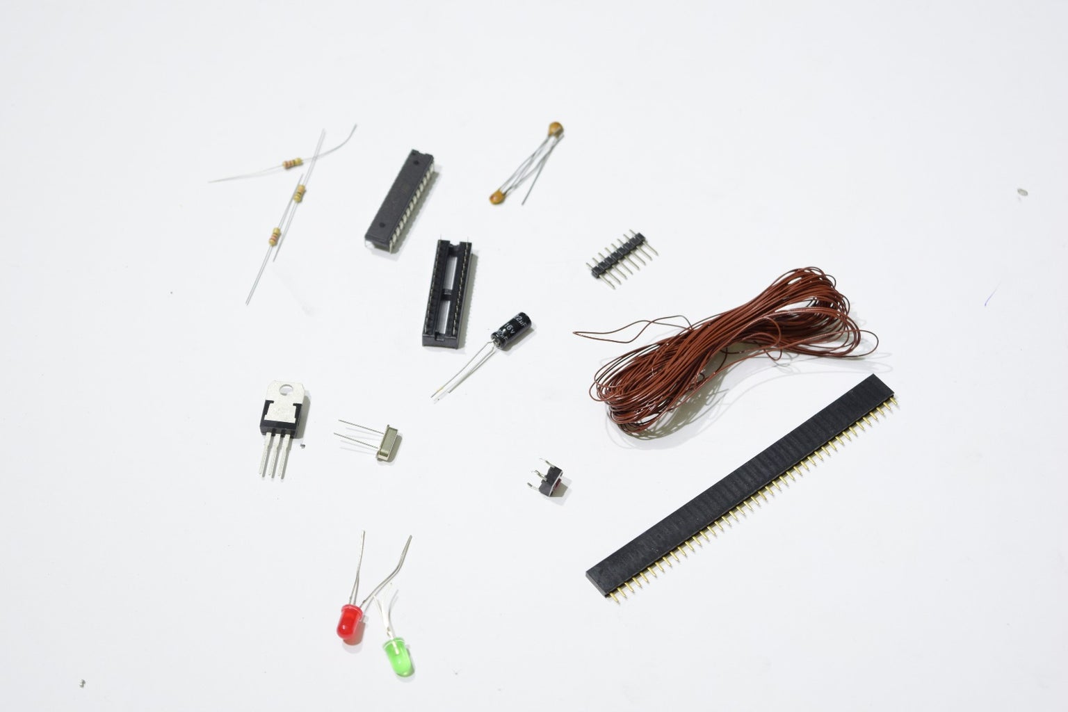
Circuit Building
- Atmega328 with bootloader installed or you can install bootloader
- 16 MHz Cristal
- 22pF Capacitor
- 28 Pin Narrow IC Base
- 4 Pin Puch Button
- 5.1 mm DC Jack
- Male and Female Headers
- 5mm Led
- 220 Ohm Resistor
- 10K Ohm Resistor
- Jumper Wire
- LM 7805 Voltage Regulator
- 10 uF Capacitor
Programming
- USBASP with latest Firmware for programming
- Connecting Wires
- Arduino Board for Burning Bootloader or a USBASP
- PL2303 for Serial Communication
Step 2: Design Notes


- The PCB Layout as i mentioned earlier is made exactly according to the Arduino Uno design so that compatibility is maintained.
- The board has simple through hole components.
- I tried to keep the PCB as efficient as possible but there are still redundancies which i will remove in the future.
- Led's for power and pin 13 are also present.
- ICSP header for programming the board using USBASP is placed.
- I didn't place a dedicated header for serial communication as that can be done simple by four connections to the headers.
- For the more advanced people the PCB design in ExpressPCB is attached. You can download the software from here and amend the design.
Attachments

Step 3: PCB Making : Toner Transfer


- First step in making the Beeduino is to make the pcb. For that we need you need to print the image of the pcb on a piece of glossy paper.I used butter paper but you can use magazine paper aswell. Make sure you print it with the correct paper type. Print it using a toner printer as inkjet printer wont do.
- Now you have to cut your copper clad board to 8cm x 6cm size. I used my handmade scoring tool. After marking the board using a sharpie and measuring tape score the copper side with a ruler as a guide. Score a fair amount and then snap against an edge
- After that clean up the copper surface using fine grit sandpaper. I used 300 grit. Sand it until its nice and shinny. This is important as it will improve the transfer.
- Next place the cladding on the printed PCB making sure its center and secure it with tape. I used paper tape but later found scotch tape to work even better.
- Now the ironing part. I have read many people saying medium heat but i found full heat to work best. Heat up your iron to the max and then start ironing the PCB and paper complex. Iron on the paper side. You will start to see the traces appear. Move the iron round and about to evenly heat all areas. To this for about 5 mins.
- Lastly you have to remove the paper. Without disturbing the paper put it under running tap water. Soon the paper with start to get soggy. With the help of your fingers slowly rub off the paper. There will be a plastic layer as well. Remove that gently so that the traces are not disturbed.
- You should now have a good transfer. If it isn't up to mark then sand away and retry.
Attachments

Step 4: PCB Making : Etching


There are numerous ways one can etch a PCB. Etching is basically to remove the exposed copper of the clad in order to make a circuit board.
- The most common and widely used which was also used by me is ferric chloride etchant. Its simple actually. Place the etchant fluid in a tray like container. If you have solid ferric chloride then add water about 2 cups and add the ferric chloride until the color is a opaque brown while mixing it continuously. After that place the PCB in the solution and move one side of the tray up and down to agitate the solution. Keep checking at regular intervals and after about 5 mins the PCB will be etched. You will know this as all the exposed copper will disappear and only the black traces will remain.
- Another etchant is muriatic acid which is basically hydrochloric acid. Using non-reactive measure cups, mix 2 parts hydrogen peroxide and 1 part muriatic acid. Dip the board and see the magic. It will be ready in less than 2 minutes
- Finally you can also use vinegar, hydrogen peroxide and salt.The mix is about 60% vinegar and 40% hydrogen peroxide, with a good shake of regular salt . Dip the board and after about 20 to 30 min the board will be ready.
For all the above safety first so wear gloves and after the etching is done rinse it in tap water.
Step 5: PCB Making : Drilling and Finalizing


Next is to drill the PCB. It is best to drill using a small drill press but since i didn't have one i used my hand drill. Also my drill bit was a bit wide which caused me troubles so make sure you use the correct diameter. At this point the toner is still not removed.
When all the holed are drilled, double check to make sure you didn't miss any. Then used the sandpaper to sand away the toner and uneven surface near the drilled holes.
And your PCB is now ready.
Step 6: Circuit Building


Now we move on to build the circuit which involves soldering all the components in their right place. The first image shows the placement of the components.
- First off start with the three resistors. One 10k Ohm and the two 220 Ohm
- The solder the 28 pin IC Socket
- The Led's and 7805 voltage regulator comes in next
- Then the crystal, 22pF Capacitor and the reset button.
- Solder the four female headers and the ICSP male header.
- Next come in the 7 jumpers which are shown are straight lines in the first image. They are a bit tricky so double check to make sure the correct ones are jumped.
Now you have to perform some checks to ensure that you did all soldering correctly.
- First check is to plug in DC power and the red led should light up
- Do a comprehensive visual check of all the pcb traces and where there is double check continuity with a multi meter
- Check that correct 5v are presant at the pcb pins where they should be.
- If you have an Arduino Uno. Load the blink program in t and then insert its chip into the Beeduino. The green led should flash.
If all is well you can proceed.
Congratulations. The hardware part is all done. If you are with me up till now then lets move on the software part.
Step 7: Bootloader Burning Using Another Arduino
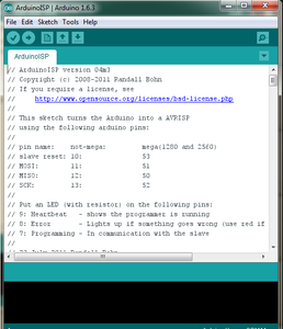

Boot loader on a micro controller is basically its operating system. It tells it how to communicate and respond. The arduino boot loader allows it to be programmed via USBASP. First download the latest Arduino IDE here and install it.
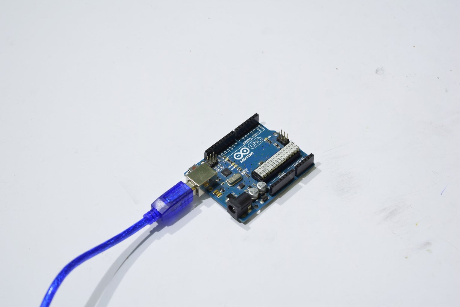
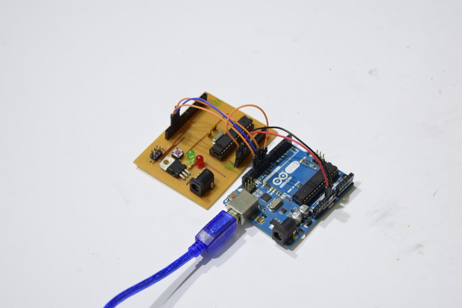
For burning the boot loader you need an Arduino Uno. Follow the following instructions carefully
- Connect the Uno and select the port. Open the example ArduinoISP and program it to the Uno.
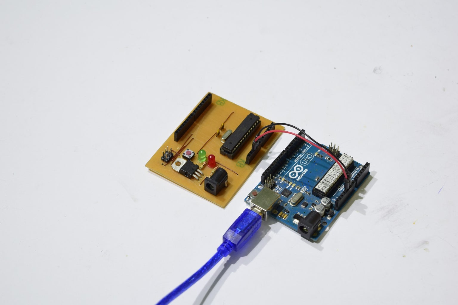
- Connect the Uno to Beeduino as shown in the second image.
- In the Arduino IDE, In Tool > Programmer, select Arduino as ISP
- Then in Tools click on Burn Boot loader. If all is well the boot loader should burn in a few seconds.
If there is a problem do the following checks.
- Double check all the connections. They should be firm.
- Remove and redo the connections.
- Recheck the board to see if you made any soldering mistake.
- Remove the USB cable from PC and reconnect, then try again.
I hope you are able to burn the boot loader successfully.
Step 8: Bootloader Burning Using USBASP


You can also burn the boot loader using the USBASP. The USBASP comes with a 10 pin connector which is useless to us so we will use female to female jumpers to make connections from the USBASP to the Beeduino ICSP header.
- First you need to download and install the USBASP driver from here.For installing the driver, plug in the USBASP in your PC. Right click my computer and open Manage. Go into Device Manager. Right click on USBASP and update driver software. Manually search driver at a certain location. Set that location to where you downloaded the drivers and click next. It will install the driver.
- Make the connections with the help of the pin outs or the images of me making them.
- Open Arduino IDE and in Tools > Programmer set it to USBASP.
- In Tools > Board set it to Arduino Uno
- In Tools click Burn Boot Loader and if all goes well the boot loader will burn in a few seconds.
What to do if an error occurs? An error can occur and you can fix it by the following steps
- Double check your connections. They should be firm.
- Redo you connections.
- Your USBASP may need to be updated. For that go here and follow the instructions.
- Driver may not be installed. Check in Device Manager.
- Remove and reconnect USBASP to PC and retry.
- Check to see if correct board is selected.
I hope you are able to burn the bootloader.
Step 9: Programming the Beeduino


Programming the Beeduino requires a USBASP. Again the same pin problem occurs so we will make the same connections are before using the jumpers. Now you must be thinking making these connections every time is so cumbersome and you are correct but this is just for the moment. Soon i will tell you how to make a fixed 6 pin header which we will just plug and program.
Once the connections are made plug the USBASP into your PC and open the arduino program. To upload it press shift and then the click the upload button while making sure the programmer is set to USBASP. It will upload the program. Pressing shift makes use of the programmer to upload the program.
This is the part your supposed to take a long breath as you have successfully made your very own Beeduino.
Step 10: Serial Communication


For serial communication between the Beeduino and a PC we need the PL2303 USB to Serial Adapter.
Download and instal its driver from here.
Connect the Beeduino to the PL2303 module.
The connections are simple. They include the power connections. Connect the RX and TX of PL2303 to theTX and RX of the Beeduino respectively.
Plug in the PL2303, the PC should recognize it. Open the Arduino IDE and then the serial monitor to view the serial data.
Step 11: 10 Pin to 6 Pin ICSP Header


Following the pin arrangements of the two solder the six wires from the 10 wire ribbon.
The wires are numbered from 1 to 10 on the ribbon,1 being the pink shade.
Place a piece of tape on the top side of the 6 pin header in order to know its orientation.
Step 12: Labels : Optional


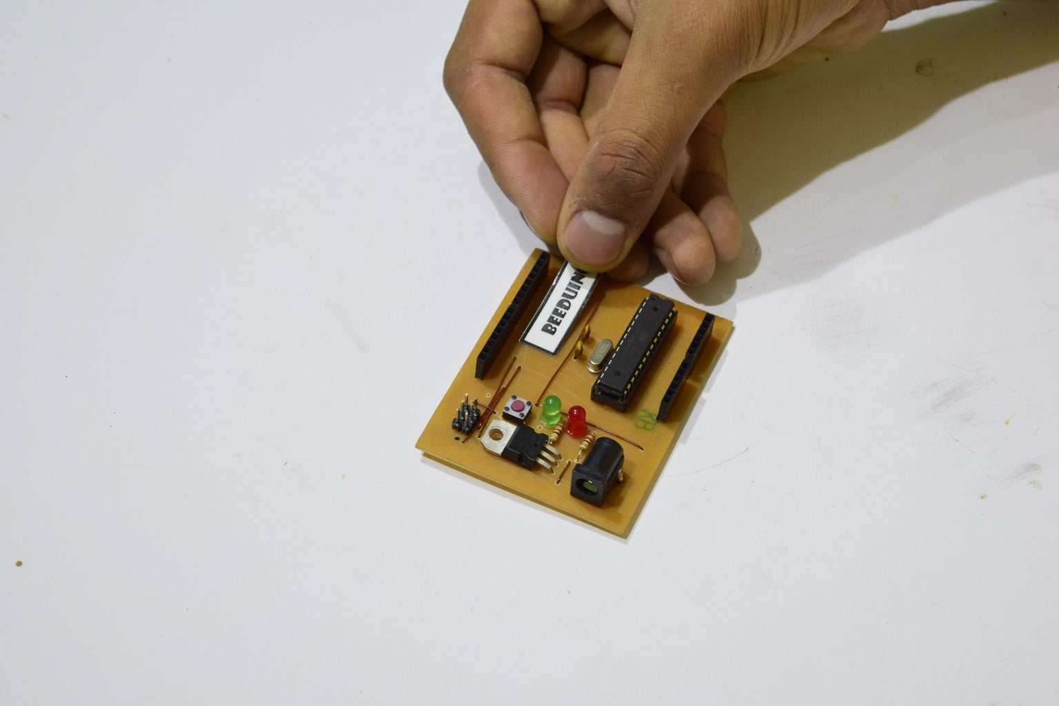


Now this is purely optional but it really helps in prototyping. I added labels for the pins on the side of the headers.
- Print out the word file
- Stick clear scotch tape on the front
- Stick double sided tape on the back
- Cut them out
- Sick them on the Beeduino as shown
Attachments
Step 13: Conclusion

This was a very successful project and i am very happy with the ease of use and programming of the Beeduino as well as the cost. Although it took some effort to make the first one but i am planning to make them in greater number which would make it even faster to build them.
Future prospects include improving the PCB design and manufacture process.
Thank you for viewing and please comment you thoughts.

Runner Up in the
Home Automation


