

Introduction: Robot Beetle Ringo


I want to introduce Beetle Ringo. That’s a six-legged robot controlled by any IR remote (some TV remote e.g.) you can find around.
It is a small and easy weekend Arduino project with big ambitions: on the one hand you don't need any complicated parts or smart skills to make it and on the other hand this is a real mobile robotic platform. It will take you only a day to build it and you can spend many days developing it. I hope this project will be useful for beginners: we can make these first steps together and have the robot you can improve in future.
The photo you see above is my previous release of the robot. It is very easy to make it, but this time I want to simplify it even more. I decided to avoid soldering. A lot of beginners are afraid of it. I can understand them: new tools, materials, experience. The project will become a headache if you see a soldering iron for the first time. So let's exclude it!
Another common beginner's fear is programming. Beetle Ringo is a real robot and of course it has a program. But this program is already completed and you can find it and download from the project's page on GitHub. This is an opensource project and you can fork it (copy the source code) and modify it as you wish. At this point Ringo could be a good start to learn programming.
Step 1: Preparing


What we should know to make Ringo?
It will be great if you are familiar with Arduino platform. If you don’t never mind. It’s the best time to learn about it. I can give you some links. First of all take a look at the Arduino website. It is also useful to read Arduino wikipedia page. You will find a lot of new words there but you can dive deeper through the links. I advise you to watch video tutorials by Jeremy Blum. They are short – 15–20 minutes, simple and I think that's one of the shortest way to Arduino world. And the last thing about Arduino platform I want to say: Arduino is an amazing project with huge community. I'm almost sure that any question you get was asked before. So Google will help you.
What parts do we need to make Ringo?
- Arduino Uno controller with USB cable.
- Battery case with ON/OFF switch for one 9V battery. This would be a bearing part of the robot. I made a photo to show what kind of battery case do you need exactly.
- 9V alkaline battery or 7.2V – 8.4V accumulator. Pay attention that Zinc-carbon batteries can't give enough current so don't use them.
- Three small analog servos. I used HXT500. And you can take any servos of the same size and 5V voltage.
- One infrared (IR) receiver. Most of IR remotes work on 36kHz, 38kHz or 40kHz. Only Sharp, Bang&Olufsen use exotic currier frequencies 56kHz and 455kHz. Well... I lied when I said that you could use any IR remote. You should select IR receiver according to IR remote you're planning to use. But! If you don't plan to use Sharp or Bang&Olufsen then you can choose any currier frequency among 36, 38 or 40kHz for your IR remote. For example I used IR receiver TSOP2136 (36kHz) with Sony IR remote (40kHz). And everything worked fine. So for most of IR remotes you can take these receivers: TSOP21xx, TSOP22xx, TSOP312xx where “xx” is 36, 38, or 40.
- Mini-sized solderless breadboard. Or you can take a big one. In any case we are going to cut it and make even smaller than mini-sized.
- Jump wires.
- Steel wire for legs. Diameter 1.5 – 2 mm (0.06” – 0.08”).
- 2–3 common metal paper clips. The size doesn't matter but the diameter of the wire should be something around 0.9 mm (0.035”).
And these are tools we need for Ringo
- Hot glue gun with glue sticks.
- Hacksaw or Dremel with cut-off wheel.
- Flat needle file or Dremel with grinding stone.
- Flat-nose pliers.
- Diagonal pliers.
Step 2: Learning to Communicate With IR Remote


Let’s learn how we can receive commands from IR remote. The goal is to get and remember signal codes of your remote. We will use them later in the Beetle Ringo’s sketch.
Take an Arduino Uno, a breadboard (its size doesn’t matter on this step), jump wires and an IR receiver. Make a circuit you see on the pictures.
WARNING! This circuit is made for IR receiver TSOP2136. Yours can differ. Check the datasheet for your receiver first.
Now follow the link and download the source code. If you worked with Git repositories before then you can fork or clone this one. And if you haven’t then you can just download ZIP archive of the sources directory and unpack it somewhere to your local drive.
Start Arduino IDE and open project /ir_receiver/ir_receiver.ino. Take a look at the code. The first line of code is
#include "IRremote.h"
That means that the sketch uses a special library IRremote.h that implements functionality of receiving and sending (we don’t use it) IR signals. This library is not a part of Arduino IDE and we need to install it. It is an open project with GNU license so we can use it for Ringo. Read the instruction and install the library. Don’t forget to restart Arduino IDE and reopen ir_receiver.ino.
Now we are ready to upload the sketch. Connect your computer and Arduino Uno via USB cable.Check menu item Tools⇒Board in Arduino IDE. It should be set to “Arduino Uno”.
Then check menu item Tools⇒Serial Port. It should be set to the port your controller is connected to.
Compile and upload the sketch (File⇒Upload).
Then open Serial Monitor (Tools⇒Serial Monitor) and check it’s baud rate. Set it to 9600.
Take an IR remote and start to press buttons. Everything works fine if you see codes in the Serial Monitor.
About these codes… As I said we will use them in the sketch that control the robot. Various vendors use different communication protocols. So codes and code sequences can differ for different IR remotes. And it will be hard to understand them all. But I want to simplify the problem. When you press a button you can see that several codes appear in Serial Monitor window. Some of them recur, others are unique. We need only these unique codes. And let’s ignore codes that recur. Some vendors use protocols where there is one unique code for each button. Other vendors use protocols with two interlaced unique codes for a single button. I mean that when you press the button for the first time you get one code, when you press it for the second time you get another code. Then when you press it for the third time you get the first code again. And so on.
Our robot can execute 13 commands:
- Move forward.
- Move backward.
- Turn left.
- Turn right.
- Move forward with left turn.
- Move forward with right turn.
- Move backward with left turn.
- Move backward with right turn.
- Stop.
- Set the 1st speed (the slowest).
- Set the 2nd speed.
- Set the 3rd speed.
- Set the 4th speed (the fastest).
Now press each button several times and write all unique codes to the table with two columns: button and codes. You will use these codes in the sketch that controls the robot.
Step 3: Prototyping


I highly recommend to check the robot’s sketch and all hardware components before you start assembling.
Take a look at the pictures. I have attached two circuits. They are equal but one is big and clear and the other is small and terrible. We have to make the terrible. You can see that I used only a small area of breadboard there – 5x10 pins. That's the size of the breadboard we'll mount on the robot latter.
Open sketch /ir_ringo/ir_ringo.ino in Arduino IDE. We’ve got all source code on the previous step. You see that there’s two tabs in editor window: “ir_ringo” and “ir_command_codes.h”. I divided the sketch in two parts: common sources and personal IR codes constants. Before you start to upload the sketch change my IR codes to yours. You’ve saved them in a table on the previous step. As I said before each command can be assigned to several unique codes. You can use this feature to use more than one IR remote to control the robot.
After you have changed the codes you can upload the sketch to the controller. When the sketch starts all servos move to the 90° position.
Now let's test our prototype. Press "forward" button on the IR remote. You will see that all three servos have started oscillating process around 90° position. Press colored buttons and check that period of oscillating process changes. Set slow speed and press "backward". You will see that central servo has changed its phase.
Don’t forget to check the battery and on/off switch on the battery holder. Unplug USB cable from Arduino Uno and connect battery holder to it. Make sure that red wire (positive) is in “Vin” pin and the other wire (negative) is in “GND” pin of the controller. Turn on the power switch on the battery holder and run our previous test.
Step 4: Beetles Tripod Gait
You can skip this step because it is not exactly about making the robot. I just want to say some words about beetles' gait and the algorithm to emulate it.
The idea to add this step came to me because not all of my friends know how beetles walk. I asked them risking to loose them.
Well... Beetles typical for insects have six legs. Even my friends heard this, I guess. And the key is that bugs always stay on three of their legs while walking. Two (front and hind) on the one side and middle leg on the other. That's the most stable position and they don't need to balance and think. Lucky beetles. They make a step and then they change their legs. This walk is called a tripod gait.
I know that seeing is believing and when I was searching for a video to demonstrate this gait I found out that this is not the only beetles' gait. They can gallop! Unfortunately Ringo cannot. Anyway this video shows both types of beetles’ gait.
How can we implement a tripod gait? Ringo has three servos. They are set in a row from his left side to right. Left servo is for left front and hind legs. These legs are made as a single part. Right servo is for right front and hind legs. And central servo is for middle legs. This video demonstrates how servos move. Turn captions on!
Left servo can push Ringo's left side in forward or backward direction. The same story with right servo on the right side. The purpose of central servo is to tilt Ringo to the left or to the right to let servos on the sides do their job.
As you see all three servos perform oscillating processes. The goal of our sketch is to provide amplitude, period and phase control of oscillating.
You don’t need to enter into mathematics but if you want to I have made a tiny simplified sketch to demonstrate how oscillating is implemented.
Press Play button on the circuit above and you will see the sketch emulation. To download this sketch go to the project's page.
And by the way! Thanks to Autodesk, Inc. and www.instructables.com I unexpectebly found this absolutely amaizing service 123d.circuits.io.
This "thanks" is sincere and it is not because I'm going to take part in the contest conducted by 123d.circuits.io. Well... eh... I'm going... But my "thanks" is frank!
Step 5: Mounting Arduino Uno


The bearing part of the robot is the battery holder. All other components we’ll mount on it: controller, servos and a tiny breadboard.
And the first part we are going to mount is the controller. The easiest way is to use a hot glue. That works but I don’t like it. To use a glue means that Ringo will grab my controller forever. So if you are greedy like I am then you can take a paperclip and make a very simple bracket.
Print the stencil. You can find measure lines on it. Take a ruler and check the lines’ length. If length is wrong then explore and try to correct settings in your pdf-viewer.
Unbend the paper clip and then bend it following the stencil. Plug the bracket we’ve made into digital I/O pins 9 and 12. Take a hot glue gun and glue the bracket to the bottom side of the battery holder. I recommend to position the battery holder in the way when it’s on/off switch is on the rear bottom side of the robot.
And don’t worry about bridging pins 9 and 12. That’s safe, we won’t use them in our sketch.
Attachments

Step 6: Tiny Breadboard


I recommend to use breadboard as small as possible. The smaller breadboard the lighter it is. We already proved that 5x10 pins is enough for Ringo. And I know two ways how you can get such a breadboard.
The 1st one: you can buy it. Type “tiny breadboard kit” in browser and you will find the same Lego-like blocks as you see on my photo. Yes, I’m lucky, I have some. The blocks are 5x5 pins. There’s 10 blocks in a kit and we need two. Glue them and 5x10 pins breadboard is ready. But there’s a downside: these breadboards are uncommon. And maybe you couldn't find them near your home.
If so there’s the other way: DIY. Let’s take a common breadboard (any size you have) and cut it to 5x10 pins size. I decided to choose this way because I often choose the wrong way.
On the bottom side of the common breadboard there is a mounting tape. If we take it off the breadboard falls to pieces. But I recommend to take off some strip areas just where we are going to make cuts.
Now take a hacksaw or Dremel to cut the breadboard. Use flat needle file or Dremel with grinding stone to sharpen the cuts.
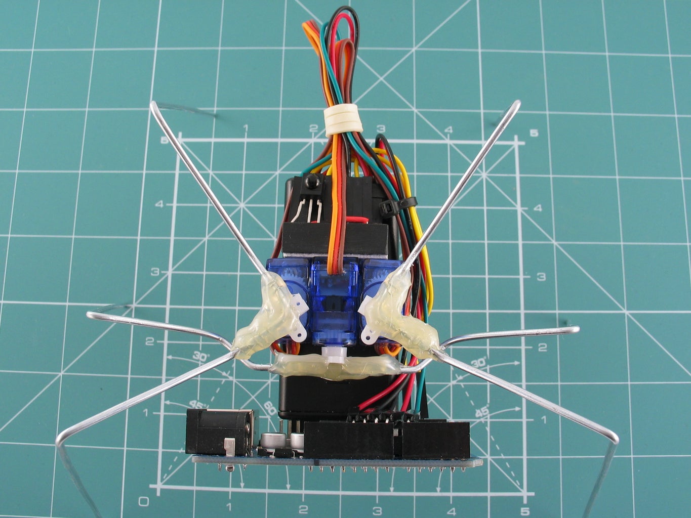
Step 7: Assembling


First of all we are going to mount three servos on the top of battery holder. Take off the stickers from the sides of our servos – we are gluing servos, not stickers.
Cut off mounting tabs, we don't need them and they are taking too much space. Be careful, servo cases are very breakable.
Take one servo and glue it to the top of the battery holder. This would be central servo for middle legs. It's output shaft should be directed towards the controller. Try to position the servo the same way as you see on my photos. Note that we should leave some space for a tiny breadboard beside the servo and some space in front of it to mount middle legs.
Glue two other servos to the battery holder and to the sides of the first one but turn their output shafts up.
Now let’s mount our breadboard. Take off the sticker that protects the tape’s glue. I don’t trust this tape so I recommend to put some hot glue right above the tape’s glue and to one long side of the breadboard. Check the photos to see the result.
Repeat the circuit you’ve made on the prototyping step. I attached the picture of it to this step again. Note that IR receiver should be directed up.
I faced two difficulties while connecting the wires to the controller. The first one is that my jump wires had too long connectors. And when I plugged them to +5V, GND and A0 pins my servos couldn't move. To solve this issue just bend the connectors at 90°.
The other difficulty is that the wires from battery holder are too thin. I couldn't fix them in Vin and GND pins of the controller. The fast and easy solution is to double flat the wires. I tried it (you can see on the photo) and it works. But frankly I’m afraid that these wires could be broken if to plug and unplug the connections for several times. That’s why I used connectors - the same connectors as on the jump wires.
Now turn on the switch on battery holder, take the IR remote and check that Ringo works. After you send stop command the sketch will move servos to zero position (90°). It is a safe position to mount servo horns. I suggest to use cross horns. The horn for middle servo should be oriented horizontally. And the horns for left and right servos should be oriented at 45° to the sides. Check the photos.
Don’t forget to screw servo horns. And cut off long inner parts of the horns that can conflict to each other while moving.
Step 8: Making Legs


I've made stencils to help you with the size and shape of Ringo’s legs. Print them and check the scale as you did before. One stencil is for left and right front-hind legs. They are absolutely the identical and it doesn't matter whether you mount one front-hind leg to the left or to the right servo. The other stencil is for Ringo's middle legs.
Attentively explore the pictures above. I've made photos with marks that will help you to understand the stencils. You can see named points that are used in stencils to mark the intervals of steel wire. Follow stencils' steps and bend wire.
Two remarks about middle legs.
- The shape of these legs is a little bit more complicated than the stencil. So bend the steel wire following the stencil and after that look at the top view photo and correct the shape. If you don’t do that middle and front legs can collide.
- I made these legs in the stencil longer than they should be. It’s better to cut some wire than let middle legs hang in the air.
Now the final straight! You should hot-glue these legs to the servo horns: first front-hind legs, than middle legs. Be neat but don’t worry if you make a mistake. To correct it just warm the glue again.
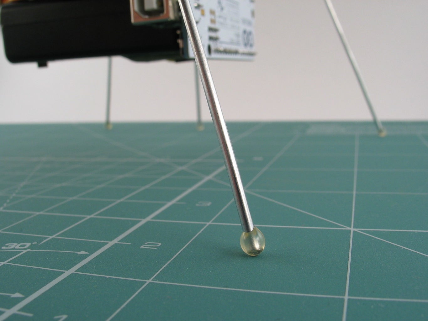
If you don’t plan to scratch your floor then drip a drop of hot glue on Ringo’s legs. I’ve made the photo.
Step 9: Conclusion
It is easy to make a simple robot but it’s impossible to complete it. I mean that the more you make – the more you want to add.
I hope Ringo could be a platform for your fantasy. You can change his appearance and modify his code. Add IR emitter and Ringo will be ready for robo battle. Add line sensor, range, tactile or any other Arduino-compatible sensors. Implement obstacle avoidance. Try to mount a tiny webcam. Change IR receiver to Bluetooth adapter and make Android or iOS apps to control Ringo. You can invent millions ideas and improve Ringo as you wish. And at the same time you will learn a lot of new things and that’s the way Ringo can say thanks to you.
And for desert Beatle Ringo sings!
P.S.
English is not my native language, so if you see my slips, if you ha-ha or even smile, please send me a private message because Ringo and me are very cool and serious. We’ll correct the text immediately. I am a programmer and more or less familiar with “soft” English words, but all these “hard” “output shaft” and “diagonal pliers”... that’s some kind of gibberish for me. Oh… now I’m sitting with a serious face repeating these words in German style. They are realy hard!
P.P.S.
123D Circuits implemented IR Remote and IR sensor! I just "draw" another breadboard, added my code and it works! Why didn't they add glue and legs to the library? Anyway, that's amazing service. Now we can see all Ringo's tricks in the emulator.

Participated in the
123D Circuits Contest

Participated in the
Makerlympics Contest


