

Introduction: Beginner Arduino


The Arduino is a pocket-sized computer (also called a "microcontroller") that you can program and use to control circuits. It interacts with the outside word through sensors, leds, motors, speakers... even the internet; this makes it a flexible platform for lots of creative projects. Some popular uses include:
- programmable light displays that respond to music or human interaction
- robots that use information from sensors to navigate or perform other tasks
- unique, customizable controllers and interfaces for music, gaming, and more
- connecting real world objects to the internet (twitter is especially popular)
- anything interactive
- automating and prototyping
There are tons of amazing Arduino Projects posted online, here are some of my favorites:
Twitter Mood Light by RandomMatrix, a light that changes color depending on what kinds of emotional words are trending on Twitter
Nebulophone Synth by Bleep Labs:
Singing Plant by Mads Hobye:
Polargraph Drawing Machine by Sandy Noble:
Flame-Throwing Jack-O-Lantern by Randy Sarafan and Noah Weinstein:
Rain-sensitive light up umbrella by snl017
There are quite a few microcontrollers on the market today, but the Arduino stands apart from the rest becuase of the active online community around it. If you search on google or youtube, you will find tons of great project ideas and information to get you started. Even though you might not have any experience programming or working with a microcontroller, the Arduino is simple to get up and running, and it's a fun way to learn about electronics through experimentation.
This Instructable was written for an Intro to Arduino class I'm teaching at Women's Audio Mission this month. I'll be posting Instructables on more advanced Arduino topics and on building customizable MIDI controllers with Arduino in the next few weeks as the class continues. More info about Arduino can be found on the Arduino reference page.
For this class you will need:
(1x) Arduino Uno Amazon or you can pick one up at a local Radioshack
(1x) usb cable Amazon
(1x) breadboard (this one comes with jumper wires) Amazon
(1x) jumper wires Amazon
(4x) red LEDs Digikey C503B-RCN-CW0Z0AA1-ND
(4x) 220Ohm resistors Digikey CF14JT220RCT-ND
(1x) 10kOhm resistor Digikey CF14JT10K0CT-ND
(1x) tact button Digikey 450-1650-ND
(1x) 10kOhm potentiometer Digikey PDB181-K420K-103B-ND
(1x) RGB LED (common cathode) Digikey WP154A4SUREQBFZGC
Tips on ordering stuff: Digikey is usually the cheapest place you can get components and they ship really fast, but sometimes it's difficult to find what you're looking for because they have so much stuff. If Digikey gives you too much trouble try Jameco, you'll pay a few cents more per component, but it's a lot easier to navigate their inventory. If you need stuff right away, you can find components, breadboards, cables, and Arduinos at your local Radioshack, but you will usually pay a bit more. Adafruit and Sparkfun are good online store for finding cool sensors or other Arduino accessories and they usually have tutorials and sample code for their more complicated parts. Amazon is also a good place to check, right now they have Arduino Unos for $22, which is the cheapest I've ever seen them.
In this Instructable I'll be using 123D circuits to demonstrate and simulate the circuits, the embedded circuit simulations work best with the Chrome browser.
Step 1: What Is Arduino

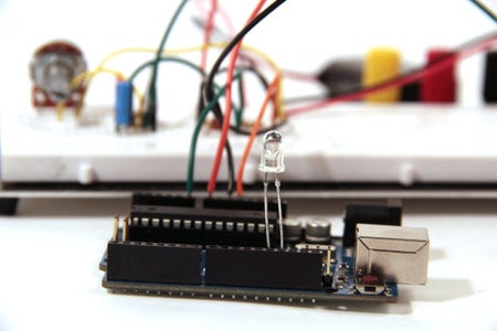
First we'll take a look at all the parts of the Arduino. The Arduino is essentially a tiny computer that can connect to electrical circuits. The Arduino Uno is powered by an Atmega 328P chip, it is the biggest chip on the board (see the image note on the image above). This chip is able to execute programs stored in its (very limited) memory.
We can load programs onto the chip via USB using the Arduino IDE (download this if you haven't already). The USB port also provides power to the Arduino. Alternatively, we could power a programmed board using the power jack, in that case we do not need a USB connection.
The Arduino has a few rows of pins that we can plug wires into. The power pins are labeled in the image above. The Arduino has both a 3.3V or 5V supply; in this class we will use the 5V supply, but you might find some chips or components that require 3.3V to run, in that case the 3.3V supply will be useful. You will also find some pins labeled "GND" on the Arduino, these are ground pins (ground is the same thing as 0V). Electrical current always flows from some positive voltage to ground, so these pins are useful for completing circuits, we will use them often.
The Arduino has 14 digital pins, labeled 0-14, that connect to circuits to turn them on or off, or to measure buttons and other 2-state circuits (a button is two state because it is either pressed or not pressed, as opposed to a dial, which has a range of possible states). These pins can act as either inputs or outputs, meaning they can control a circuit or measure it.
Next to the power connections are the Analog input pins, labeled A0-A5. These pins are used to make analog measurements of sensors or other components. Analog inputs are especially good for measuring things with a range of possible values. For example, an analog input pin will let us measure the amount of flex of a flex sensor, or the amount that a dial has been turned. You can use an analog input to measure a digital component (like a button) or even act like a digital output, they are basically digital pins with extra powers.
Step 2: How to Use a BreadBoard


Breadboards let us make temporary electrical connections between components so that we can test circuits before we permanently solder them together. This whole class will be done on a breadboard so we can reuse components and make quick changes to a circuit.
Breadboards have rows of holes that you can plug wires or other electrical components into. Some of these holes are electrically connected to each other through metal strips on the underside of the breadboard. Here's how the connections work:
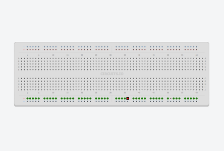
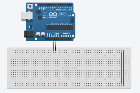
One each side of the breadboard, two rows of holes are connected across the entire length of the board (images 1 and 2 above). Generally, you will connect these long "rails" to 0V (also called "ground") and whatever voltage you are using for power (in this class we will use 5V from the Arduino), so that those connections are available everywhere on the board. In this case, the first thing you want to do is wire up these connections to your Arduino as shown in image 4, notice how I connected ground to the row labelled "-" and 5V to the row labelled "+", your breadboard may or may not be labelled. Note: sometimes these side strips will only extend halfway across a longer breadboard, use wires to complete the connection (image 5).
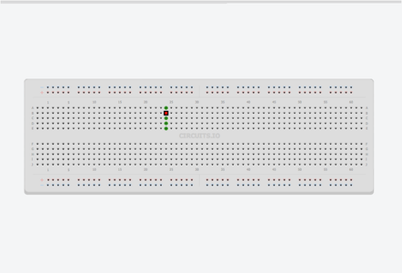
The rest of the holes in the breadboard are grouped into rows of five in the center of the breadboard (image 3). This is where you will connect electrical components to each other to form circuits.
Step 3: Turn on LED With 5V


As I explained before, electrical current flows from high voltage to low voltage. In this class we'll be powering everything off of 5V from the Arduino, so current will flow from 5V out of the Arduino, through our circuit, and back into the Arduino's "ground" pin. The first thing we'll power up is an LED.
The circuit that turns on an LED involves two components: a resistor and an LED. The schematic representation of the circuit is shown in image 4 above. The resistor is represented by a rectangular box (you might also see it represented by a zigzag line). The LED is represented by a triangle with a line, and usually some arrows pointing outward that represent light coming out of the component.
So why do we need the resistor in this circuit? This resistor is called a current limiting resistor, this means the resistor limits the amount of electrical current that flows through the LED. Every LED is rated for a certain amount of current, if you go over that amount you will probably damage the LED. Using Ohms Law, we can calculate the value of the current limiting resistor we should use with our LED.
Ohms Law is very simple, it says that there is a linear relationship between current and voltage in a resistor: increasing the voltage across a resistor will increase the current that flows through it. Specifically it says:
V = I * R
where
V = voltage across the resistor
I = current through the resistor
R = resistance - this is what we want to calculate
so if we know the values of V and I, we can calculate the correct R for our circuit
First we need to calculate the voltage across the resistor. In the circuit shown in image 4, a total of 5V is applied to the circuit. Most of the 3mm or 5mm LEDs you will use require 3V to light up, so the remaining 2V (5V - 3V = 2V) is applied across the resistor.
Next we calculate the current going through the resistor. Most 3mm or 5mm LEDs run at full brightness at about 20mA of current; going over this could damage the LED, and going under this will make the LED glow dimmer (but does no harm). Assuming we want to run our LED at 20mA, we know that the same amount of current must run through the resistor since the components are wired together in series. This leaves us with:
2V = 20mA * R
2V = 0.02A * R
R = 100 Ohms
So 100 Ohms is the absolute minimum resistance we need to make sure that we do not damage the LED. To be safe, it's a good idea to use something a little higher, just in case your LED has slightly different ratings that what I've used here. I like to use 220Ohms because I always seems to have a lot of those around. If you know the ratings of your LED (you can find it on the LED's datasheet) and you want to do this calculation yourself, you can also try using an online calculator.
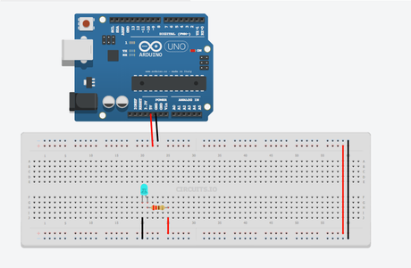
Next we'll wire up the LED on the breadboard. Plug the resistor and the LED into the central part of the breadboard so that the longer lead of the LED is electrically connected to one of the resistor's leads (image 3). Then connect the remaining end of the resistor to 5V and the remaining end of the LED to ground. You should see the LED light up.
Some things to try:
Notice how the LED's leads are not the same length, this is because LEDs need to be in a circuit in a specific orientation in a circuit. Current always flows through LEDS from the long lead to the short lead (in the schematic representation, current flows in the same direction that the triangle points, here is a nice graphic of that). Try flipping the orientation of your LED - you should find that the LED will not light if it is placed in the circuit backwards.
Resistors, on the other hand, do not have an orientation, you'll notice that their leads are the same length (their schematic representation shows this symmetry as well). Flipping the orientation of a resistor in a circuit will have no effect on the circuit - try it.
Now try swapping the position of the LED and the resistor in the circuit (image 5). You should find that this also does not effect the circuit. It does not matter if the current limiting resistor is on one side of the LED or the other, it will still be effective in protecting the LED against excess current.
Step 4: Anatomy of an Arduino Sketch
Programs in the Arduino language are called "sketches". An Arduino sketch is comprised of two main parts: the setup function and the loop function.
setup() - the setup() function is automatically executed at the very beginning of an Arduino program. Inside this function you will initialize variables, pins, and any libraries that you might be using in your sketch. The setup() function is only run once during an Arduino sketch, right when the board is powered or reset.
loop() - the loop() is where the bulk of your program will live. This function is executed after the setup() is complete. The Arduino will execute the commands inside the loop over and over again until the board is powered off.
From here on out, the Arduino reference page will be very useful for documenation about the Arduino language and programming environment.
Step 5: Arduino LED Blink
pinMode(pinNumber, mode) - pinMode is used during the setup() part of the sketch to initialize each pin we are using as either an input or an output. We cannot read or write to a pin before pinMode has been set. pinMode() takes two arguments - a pin number (each of the Arduino pins is labelled with a number) and that mode that we want the pin (either "INPUT" or "OUTPUT"). In the case of blinking an LED, we are sending data out of the Arduino to control the state of the LED, so we use "OUTPUT" as the second argument.
digitalWrite(pinNumber, state) - digitalWrite is a command that lets us set the voltage of a pin to either 5V or ground (remember "ground" is synonymous with 0 Volts). In the last example we hooked up an LED to a 5V supply and saw it turn on, if we hook up the LED to one of the Arduino's digital pins instead, we can turn the LED on by setting the pin to 5V and off by setting the pin to ground. digitalWrite() also takes two arguments - a pin number and the state of the pin ("HIGH" for 5V and "LOW" for ground).
delay(timeInMs) - delay pauses the program for a given amount of time. For example, delay(2000) will pause the program for 2000 milliseconds (2000 milliseconds = 2 seconds), delay(100) will pause the program for 100 milliseconds (1/10 of a second), and so on...
Below is the LED Blink code, run this code on your Arduino.
//LED Blink

int ledPin = 7;//the Arduino pin that is connected to the LED

void setup() {
  pinMode(ledPin, OUTPUT);// initialize the pin as an output
}

void loop() {
  digitalWrite(ledPin, HIGH);//turn LED on
  delay(1000);// wait for 1000 milliseconds (one second)
  digitalWrite(ledPin, LOW);//turn LED off
  delay(1000);//wait one second
}
A few notes on the code:
Lines that start with "//" are comments - Arduino ignores these.
You may have noticed all the semicolons, semicolons are used at the end of every command in the Arduino language. If you forget a semicolon, you will get an error. You will find that many other programming languages use semicolons at the end of each line.
In this code "ledPin" is a variable. Variables are used to store information in programs, in this sketch, I'm using the variable "ledPin" to store the number 7. Later in the program when the Arduino hits a line with the variable "ledPin", it will evaluate the variable according to its current stored value. So the line:
pinMode(ledPin, OUTPUT);
is evaluated by Arduino as:
pinMode(7, OUTPUT);
In fact, we could replace all uses of pinMode with the number 7 and the program would work exactly the same, but using the variable helps us more easily read and understand the code.
"int" from the first line is a data type - in the Arduino language, you must always initialize variables by declaring their type. There are many different types (you can read about all of them here), for now all you need to know is that int variables are positive or negative whole numbers - you will use them often.
Below is a simulation of the sketch, try pressing the play button to see how it works (works best in Chrome)
As expected, the LED turns on for one second, then turns off for one second. Try changing the length of the delay() to see how it affects the LED blink time.
Another thing to look out for - a mistake that people often make is to omit the last delay() in the loop(). Try it - you will find that the LED stays on without blinking. This might be confusing to you, because we still have a digitalWrite(ledPin, LOW) command in the program. What's happening here is the led is turned off, but the Arduino immediately hits the end of the loop() and starts executing the first line of the loop() again (turning the LED on). This happens so fast that the human eye cannot see the LED turn off for that brief moment while the loop is restarting.
Step 6: Controlling Multiple LEDs With Arduino
In this example we'll wire up three more LEDs like we did in the last example, and control them with multiple digital pins. First wire up three more LEDs and current limiting resistors as shown below:
If we want to cycle through all the LED's and turn them on and off one by one we can write our Arduino sketch like this:
//Multi LED Blink

int led1Pin = 4;
int led2Pin = 5;
int led3Pin = 6;
int led4Pin = 7;

void setup() {
  //initialize the led pins as an outputs
  pinMode(led1Pin, OUTPUT);
  pinMode(led2Pin, OUTPUT);
  pinMode(led3Pin, OUTPUT);
  pinMode(led4Pin, OUTPUT);
}

void loop() {
  digitalWrite(led1Pin, HIGH);//turn LED on
  delay(1000);// wait for 1000 milliseconds (one second)
  digitalWrite(led1Pin, LOW);//turn LED off
  delay(1000);//wait one second

  //do the same for the other 3 LEDs
  digitalWrite(led2Pin, HIGH);//turn LED on
  delay(1000);// wait for 1000 milliseconds (one second)
  digitalWrite(led2Pin, LOW);//turn LED off
  delay(1000);//wait one second

  digitalWrite(led3Pin, HIGH);//turn LED on
  delay(1000);// wait for 1000 milliseconds (one second)
  digitalWrite(led3Pin, LOW);//turn LED off
  delay(1000);//wait one second

  digitalWrite(led4Pin, HIGH);//turn LED on
  delay(1000);// wait for 1000 milliseconds (one second)
  digitalWrite(led4Pin, LOW);//turn LED off
  delay(1000);//wait one second
}
This works, and we could leave it like and everything would work great, but it is not the most efficient way to write our code. Instead, we will use a structure called a for loop to cycle through the LEDs. For loops are useful for repeating a piece of code over and over. In the case above we're repeating the lines:
digitalWrite(led4Pin, HIGH);
delay(1000);
digitalWrite(led4Pin, LOW);
delay(1000);
here's how we'll write the for loop:
for (int ledPin=4;ledPin<8;ledPin++){
digitalWrite(ledPin, HIGH);
delay(1000);
digitalWrite(ledPin, LOW);
delay(1000);
In the first line we are initializing a variable "ledPin" as 4 and telling the Arduino that we would like to cycle through values of the variable starting at 4, up to 7 (ledPin<8). The ledPin++ tells the Arduino to increase the value of ledPin by 1 each time we repeat the loop. Then we execute the lines inside the loop using the variable ledPin. So the first time ledPin = 4, and pin 4 is turned on then turned off, then ledPin is increased to 5 and the for loop starts again, this time turning pin 5 on then off, and so on... The result is exactly the same as the more verbose sketch above, where we repeated the digitalWrite and delay commands many times. Here is the full sketch:
//Multi LED Blink

int led1Pin = 4;
int led2Pin = 5;
int led3Pin = 6;
int led4Pin = 7;

void setup() {
  //initialize the led pins as an outputs
  pinMode(led1Pin, OUTPUT);
  pinMode(led2Pin, OUTPUT);
  pinMode(led3Pin, OUTPUT);
  pinMode(led4Pin, OUTPUT);
}

void loop() {
  for (int ledPin=4;ledPin<8;ledPin++){//for pins 4-7
    digitalWrite(ledPin, HIGH);//turn LED on
    delay(1000);// wait for 1000 milliseconds (one second)
    digitalWrite(ledPin, LOW);//turn LED off
    delay(1000);//wait one second
  }
}
Step 7: Fade LEDs With AnalogWrite
Wire up one of your LEDs to a PWM enabled pin, I used pin 9. Try running the blink sketch from before, but use analogWrite instead of digitalWrite to turn on the LED (see sketch below). analogWrite() takes two arguments: the pin number and the level of brightness (between 0 and 255).
//LED Blink (half brightness)

int ledPin = 9;//the Arduino pin that is connected to the LED

void setup() {
  pinMode(ledPin, OUTPUT);// initialize the pin as an output
}

void loop() {
  analogWrite(ledPin, 255);//turn LED on at full brightness (255/255 = 1)
  delay(1000);// wait for 1000 milliseconds (one second)
  digitalWrite(ledPin, LOW);//turn LED off
  delay(1000);//wait one second

  analogWrite(ledPin, 191);//turn LED on at 3/4 brightness (191/255 ~= 0.75)
  delay(1000);// wait for 1000 milliseconds (one second)
  digitalWrite(ledPin, LOW);//turn LED off
  delay(1000);//wait one second

  analogWrite(ledPin, 127);//turn LED on at half brightness (127/255 ~= 0.5)
  delay(1000);// wait for 1000 milliseconds (one second)
  digitalWrite(ledPin, LOW);//turn LED off
  delay(1000);//wait one second

  analogWrite(ledPin, 63);//turn LED on at one quarter brightness (63/255 ~= 0.25)
  delay(1000);// wait for 1000 milliseconds (one second)
  digitalWrite(ledPin, LOW);//turn LED off
  delay(1000);//wait one second
}
Try changing the brightness in the analogWrite commands to see how it affects the brightness of your LED.
Next we'll write the code so that the brightness ramps smoothly from all the way off to full brightness. We could copy the same piece of code:
analogWrite(ledPin, brightness);
delay(5);//short delay
brightness = brightness + 1;
Over and over (255 times), increasing brightness by one each time. Here's what that would look like:
//LED Blink (half brightness)

int ledPin = 9;//the Arduino pin that is connected to the LED

void setup() {
  pinMode(ledPin, OUTPUT);// initialize the pin as an output
}

void loop() {
  int brightness = 0;

  analogWrite(ledPin, brightness);//brightness = 0
  delay(5);// short delay
  brightness += 1;

  analogWrite(ledPin, brightness);//brightness = 1
  delay(5);// short delay
  brightness += 1;

  analogWrite(ledPin, brightness);//brightness = 2
  delay(5);// short delay
  brightness += 1;

  analogWrite(ledPin, brightness);//brightness = 3
  delay(5);// short delay
  brightness += 1;

  analogWrite(ledPin, brightness);//brightness = 4
  delay(5);// short delay
  brightness += 1;

  analogWrite(ledPin, brightness);//brightness = 5
  delay(5);// short delay
  brightness += 1;

  analogWrite(ledPin, brightness);//brightness = 6
  delay(5);// short delay
  brightness += 1;

  //keep repeating until brightness = 255 (full brightness)
}
Or we can use a for loop again to make the code much more concise. In the following sketch I have two loops, the first ramps the LED up from off (0) to full brightness(255):
for (int brightness=0;brightness<256;brightness++){
analogWrite(ledPin,brightness);
delay(5);
}
The second for loop ramps down from full brightness to off:
for (int brightness=255;brightness>=0;brightness--){
analogWrite(ledPin,brightness);
delay(5);
(the delay(5) is used to slow down the fade, so it takes 5*256 = 1280ms = 1.28seconds)
In the first line, we use "brightness--" to tell the for loop to decrease the value of brightness by 1 each time the loop repeats. Also notice how the loop will run until brightness>=0, by using >= instead of > we include the number 0 in the range.
//LED fade

int ledPin = 9;//the Arduino pin that is connected to the LED

void setup() {
  pinMode(ledPin, OUTPUT);// initialize the pin as an output
}

void loop() {
  //ramp LED up to full brightness (0 to 255)
  for (int brightness=0;brightness<256;brightness++){
    analogWrite(ledPin,brightness);
    delay(5);
  }

  delay(1000);// wait one second

  //ramp LED down to no brightness (255 to 0)
  for (int brightness=255;brightness>=0;brightness--){
    analogWrite(ledPin,brightness);
    delay(5);
  }

  delay(1000);//wait one second
}
And here's what it should look like (This simulation is not quite as good, but you get the idea). Try editing the delays to see how it affects the speed of the ramps.
Step 8: RGB LED and Arduino

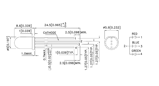

The RGB LEDs we're using in this class are common cathode, meaning all three LEDs share the same ground pin (some RGB LEDs, called common anode, share a common supply pin and have separate grounds). We'll wire up our circuit like the first image above, each LED in the RGB LED has one 220Ohm resistor in series with it that is wired up to a PWM enabled Arduino pin (I used pins 9-11). This way, we can selectively turn each LED in the RGB LED on and off individually.
See the second image above to figure out which leads of the RGB LED correspond to red, green, blue, and ground (they are numbered 1-4).
This first sketch will cycle through each color in the LED:
//RGB LED - test

//pin connections
int red = 9;
int green = 10;
int blue = 11;

void setup(){
  pinMode(red, OUTPUT);
  pinMode(blue, OUTPUT);
  pinMode(green, OUTPUT);
}

void loop(){
  //turn red led on
  digitalWrite(red, HIGH);
  delay(500);
  digitalWrite(red, LOW);
  delay(500);

  //turn green led on
  digitalWrite(green, HIGH);
  delay(500);
  digitalWrite(green, LOW);
  delay(500);

  //turn blue led on
  digitalWrite(blue, HIGH);
  delay(500);
  digitalWrite(blue, LOW);
  delay(500);
}
Then use analogWrite() and random() to set a random brightness levels for each of the colors in the LED. The three colors will mix in different proportions (depending on their brightness) to make a wide variety of colors (255^3 = 16,581,375 possible colors).
//RGB LED - random colors

//pin connections
int red = 9;
int green = 10;
int blue = 11;
void setup(){
  pinMode(red, OUTPUT);
  pinMode(blue, OUTPUT);
  pinMode(green, OUTPUT);
}
void loop(){
  //pick a random color
  analogWrite(red, random(256));
  analogWrite(blue, random(256));
  analogWrite(green, random(256));
  delay(1000);//wait one second
}
random(256); //returns a number between 0 and 255
Step 9: Arduino Functions
//RGB LED - fading between colors
//pin connections
int red = 9;
int green = 10;
int blue = 11;
void setup(){
  pinMode(red, OUTPUT);
  pinMode(blue, OUTPUT);
  pinMode(green, OUTPUT);
}
void loop(){
  for (int brightness=0;brightness<256;brightness++){
    analogWrite(red, 255-brightness);
    analogWrite(green, brightness);
    delay(10);
  }
  for (int brightness=0;brightness<256;brightness++){
    analogWrite(green, 255-brightness);
    analogWrite(blue, brightness);
    delay(10);
  }
  for (int brightness=0;brightness<256;brightness++){
    analogWrite(blue, 255-brightness);
    analogWrite(red, brightness);
    delay(10);
  }
}
The sketch above works, but there's a lot of repeated code. We can simplify by writing our own helper function that fades from one color into another color. Here's what the function will look like:
void fader(int color1, int color2){
for (int brightness=0;brightness<256;brightness++){
analogWrite(color1, 255-brightness);
analogWrite(color2, brightness);
delay(10);
}
}
Let's examine this function definition piece by piece. The function is called "fader" and it takes two arguments. Each argument is separated by a comma and has a type declared in the first line of the function definition:
void fader(int color1, int color2){
We can see that both of the arguments fader accepts are ints, and we're using the names "color1" and "color2" as dummy variables for our function definition. The "void" refers to the data type that the function returns, since our function does not return anything (it simply executes commands), we set the return type to void. If we were to create a function that multiplied two numbers and returned the product we might define it like this:
int multiplier(int number1, int number2){
int product = number1*number2;
return product;
Notice how we've declared int as the return type here instead of void.
The guts of the function is stuff we've seen before. It's the same for loop we were repeating in our last sketch, but the pin numbers have been replaced with the color1 and color2 variables. If we call:
fader(red, green);
from the Arduino's loop(), the Arduino evaluates the fader function with color1 = red and color2 = green.
Putting this all together we can rewrite the sketch using this function as follows, this will work exactly the same as the sketch at the top of this step.
//RGB LED - fading between colors
//pin connections
int red = 9;
int green = 10;
int blue = 11;
void setup(){
  pinMode(red, OUTPUT);
  pinMode(blue, OUTPUT);
  pinMode(green, OUTPUT);
}
void loop(){
  fader(red,green);
  fader(green,blue);
  fader(blue, red);
}
void fader(int color1, int color2){
    for (int brightness=0;brightness<256;brightness++){
        analogWrite(color1, 255-brightness);
        analogWrite(color2, brightness);
        delay(10);
    }
}
Step 10: Button

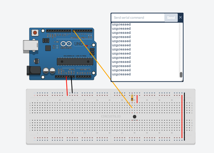
The button circuit we'll be using is made of two components - a push button and a resistor. Unlike the LED circuit, we are not concerned about the amount of current passing through the button (at very high levels of current we might have to worry about melting the button, but the Arduino is not that powerful), so the resistor is not acting like the current-limiting resistor in the LED circuit. Instead this resistor is acting as a pull-down resistor. A pull-down resistor ties a button to ground, so that measuring the voltage at the junction between the button and the resistor will always be 0V (grounded) when the button is not pressed (and the circuit is open). In this circuit, the value of the pull-down resistor doesn't really matter, I like to use something around 10kOhms.
Here is the button sketch:
//Button Press Detection
int buttonPin = 7;
void setup(){
  pinMode(buttonPin, INPUT);//this time we will set the pin as INPUT
  Serial.begin(9600);//initialize Serial connection
}
void loop(){
  if (digitalRead(buttonPin)==HIGH){//if button pressed
    Serial.println("pressed");
  } else {
    Serial.println("unpressed");
  }
}
The button sketch introduces a few new ideas:
digitalRead(pinNumber) - similar to digitalWrite(), but used to measure a value of HIGH or LOW in our circuit. digitalRead() takes one argument - the pin number that we are reading from. We must also make sure to initialize the input pin correctly:
pinMode(buttonPin, INPUT);
Serial Communication - Serial communication lets the Arduino send messages to your computer while a program is running, it is useful for debugging, sending messages to other devices or apps, or just getting a better sense of what is going on in your circuit. To enable serial communication in your sketch, you have to initialize the serial connection in the Arduino's setup() function with the command Serial.begin(). Serial.begin() takes one argument, the baud rate, which is the rate of data transfer between the Arduino and your computer, 9600 is a good baud rate for now. In the following sketch we'll use Serial.println() to print messages in the Arduino IDE (Tools>>Serial Monitor).
if/else - If/else statements gives us more control over which commands are executed when. In the button sketch I used the following if/else statement:
if (digitalRead(buttonPin)==HIGH){
Serial.println("pressed");
} else {
Serial.println("unpressed");
}
if the result of digitalRead(buttonPin) returns HIGH then the Arduino prints the word "pressed", if digitalRead(buttonPin) returns something other than HIGH (like LOW), the Arduino prints the word "unpressed". If statements can check for == ("equal to"), != ("not equal to"), >, <, >=, and <=. Try running the following if statement in the Arduino's loop():
if (4>3){
Serial.println("true");
} else {
Serial.println("false");
}
Try changing the if statement to evaluate other things.
Step 11: Arduino Digital Inputs and Outputs
//button press detection with LED output
int buttonPin = 7;
int ledPin = 8;
void setup(){
  pinMode(buttonPin, INPUT);//this time we will set button pin as INPUT
  pinMode(ledPin, OUTPUT);
  Serial.begin(9600);
}
void loop(){
  if (digitalRead(buttonPin)==HIGH){
    digitalWrite(ledPin,HIGH);
    Serial.println("pressed");
  } else {
    digitalWrite(ledPin,LOW);
    Serial.println("unpressed");
  }
}
Here is what it should look like:
Step 12: Arduino Analog Input


2.5/5*1023 = 512
analogRead() takes one argument - the name of the analog pin (A0-A5) to read from.
A potentiometer is a resistor with a pin in the middle that connects to some point along the resistor's length. As you turn the potentiometer you move the center pin along the resistor and change the ratio of resistive materials on either side of the pin. This allows the potentiometer to act as a variable voltage divider.
Connect the potentiometer so that the outside pins connect to 5V and ground (orientation does not matter), and the center pin connects to pin A0 on the Arduino. Run the following code and watch the output from the Serial Monitor.
//analog input

int potPin = A0;//center pin of the potentiometer is attached to pin A0

void setup(){
  //analog pins are initilized as INPUT by default, no need for pinMode() command
  Serial.begin(9600);
}

void loop(){
  int potVal = analogRead(potPin);//potVal is a number between 0 and 1023
  Serial.println(potVal);
}
Now turn the pot and see how the printed value of potVal changes. You should see the arduino print 1023 when you turn the pot all the way to the side that is connected to 5V, and 0 when you turn the pot all the way to the other side. You should also see a range of values printed in between those two extremes..
Step 13: Working With Analog Input Data
map(value, fromLow, fromHigh, toLow, toHigh) - scale one range to another. map() accepts four inputs: the value we're trying to scale, the min of the range we're scaling from, the max of the range we're scaling from, the min of the range we're scaling to, and the max of the range we're scaling to.
Here is an example:
//analog input with map

int potPin = A0;
int ledPin = 9;

void setup(){
  pinMode(ledPin, OUTPUT);
  Serial.begin(9600);
}

void loop(){
  int analogVal = analogRead(potPin);//analogVal is between 0 and 1023
  int scaledVal  = map(analogVal, 0, 1023, 0, 255);//scaled val is between 0 and 255
  Serial.print("analogVal = ");
  Serial.print(analogVal);
  Serial.print("   scaledVal = ");
  Serial.print(scaledVal);
  analogWrite(ledPin, scaledVal);
}
Also check out constrain(x, a, b) - constrains a number x between a and b. If x is less than a constrain returns a, is x is greater than b constrain returns b, otherwise constrain returns x.
Step 14: Practice With Arduino Inputs and Outputs
This next example combines the button detection sketch with the analog LED control sketch. Wire up a push button to pin 7, as shown in the schematic from step 10, and connect a pot to A0 and an LED to pin 9, as shown in step 13. Then upload the following code:
//button press detection with LED output and variable intensity
int buttonPin = 7;
int ledPin = 9;
int potPin = A0;
void setup(){
  pinMode(buttonPin, INPUT);
  pinMode(ledPin, OUTPUT);
  Serial.begin(9600);
}
void loop(){
  if (digitalRead(buttonPin)==HIGH){//if button pressed
    int analogVal = analogRead(potPin);
    int scaledVal  = map(analogVal, 0, 1023, 0, 255);
    analogWrite(ledPin, scaledVal);//turn on led with intensity set by pot
    Serial.println("pressed");
  } else {
    digitalWrite(ledPin, LOW);//turn off if button is not pressed
    Serial.println("unpressed");
  }
}
This sketch turns an LED off and on depending on the state of the button (pressed/unpressed), and at the same time uses the potentiometer to control the brightness of the LED when it is in the "on" state.
Step 15: Button As Toggle Switch
//Button Press Detection - single message

int buttonPin = 7;
boolean currentState = LOW;//stroage for current button state
boolean lastState = LOW;//storage for last button state

void setup(){
  pinMode(buttonPin, INPUT);//this time we will set the pin as INPUT
  Serial.begin(9600);//initialize Serial connection
}

void loop(){
  currentState = digitalRead(buttonPin);
  if (currentState == HIGH && lastState == LOW){//if button has just been pressed
    Serial.println("pressed");
    delay(1);//crude form of button debouncing
  } else if(currentState == LOW && lastState == HIGH){
    Serial.println("released");
    delay(1);//crude form of button debouncing
  }
  lastState = currentState;
}
I used something new in my if statement:
if (currentState == HIGH && lastState == LOW)
this reads as "if currentState is HIGH and lastState is LOW", && allows us to check the truth of many things in the same if statement. You can also use || ("or") to test is one thing or the other is true. Read more here.
You'll also notice the following line appears twice in the code above:
delay(1);
This delay was put in there to give the button time to settle to steady voltage before we start measuring it again, this is called button debouncing; it prevents us from counting a single press as two presses due to button chatter. Using a delay to do button debouncing is fine for this simple example, but if you were measuring a lot of buttons the delays will add up and make your code execute very slow. This might end up giving your hardware a lagging feeling. I'll address some better techniques to do debouncing later in this class.
This code also introduces a new data type: boolean. Booleans are used to store 1 bit pieces of information, things like true/false, on/off, 1/0, of HIGH/LOW. In my code I used it to store the current and last state of the button (HIGH or LOW).
Here's how we could use this to toggle an LED on and off each time the button is pressed:
//Button Toggle LED

int ledPin = 9;
int buttonPin = 7;
boolean currentState = LOW;//stroage for current button state
boolean lastState = LOW;//storage for last button state
boolean ledState = LOW;//storage for the current state of the LED (off/on)

void setup(){
  pinMode(buttonPin, INPUT);//this time we will set the pin as INPUT
  pinMode(ledPin, OUTPUT);
  Serial.begin(9600);//initialize Serial connection
}

void loop(){
  currentState = digitalRead(buttonPin);
  if (currentState == HIGH && lastState == LOW){//if button has just been pressed
    Serial.println("pressed");
    delay(1);//crude form of button debouncing

    //toggle the state of the LED
    if (ledState == HIGH){
      digitalWrite(ledPin, LOW);
      ledState = LOW;
    } else {
      digitalWrite(ledPin, HIGH);
      ledState = HIGH;
    }
  }

  lastState = currentState;
}
In the code above I set up a variable called "ledState" to store the current state of the LED, then each time the button was pressed, I used digitalWrite to set the LED to the opposite state and saved a new ledState.
Going even further, you can use the button toggle code with the fader code from the RGB LED example for the following:
//Button Press Detection - single message

//pin connections
int red = 9;
int green = 10;
int blue = 11;
int buttonPin = 7;

boolean currentState = LOW;//stroage for current button state
boolean lastState = LOW;//storage for last button state
int currentColor = red;//storage for current color

void setup(){
  pinMode(buttonPin, INPUT);//this time we will set the pin as INPUT
  pinMode(red, OUTPUT);
  pinMode(blue, OUTPUT);
  pinMode(green, OUTPUT);
  Serial.begin(9600);//initialize Serial connection
  digitalWrite(currentColor, HIGH);//initialize with currentColor on (full brightness)
}

void loop(){
  currentState = digitalRead(buttonPin);
  if (currentState == HIGH && lastState == LOW){//if button has just been pressed
    Serial.println("pressed");
    delay(1);//crude form of button debouncing

    int nextColor = getNextColor(currentColor);
    fader(currentColor, nextColor);
    currentColor = nextColor;

  }

  lastState = currentState;

}

int getNextColor(int color){//helper function that gives us the next color to fade to
  if (color == red) return green;
  if (color == green) return blue;
  if (color == blue) return red;
}

void fader(int color1, int color2){
    for (int brightness=0;brightness<256;brightness++){
        analogWrite(color1, 255-brightness);
        analogWrite(color2, brightness);
        delay(2);
    }
}
I added an extra helper function in the code above to help choose the next color to fade to:
int getNextColor(int color){
if (color == red) return green;
if (color == green) return blue;
if (color == blue) return red;
}
I declared the function with an int to tell Arduino that it should expect the function to return a number (in this case, the number of the Arduino pin that's connected to one of the RGB LED's pins. The if statements look a little different that what we've seen before, I could have written the function like this:
int getNextColor(int color){
  if (color == red) {
    return green;
  }
  if (color == green) {
    return blue;
  }
  if (color == blue) {
    return red;
  }
}
....and it would work in the exact same way. If you only need to execute one line in an if statement, you can use the shorthand:
if (something) doSomething;
without any curly braces or linebreaks.
Continue to part 2 of this series here, or learn how to hook up MIDI to the Arduino's inputs and outputs.

Participated in the
123D Circuits Contest


