

Introduction: Bench Power Supply From Old Laptop Power Supplies


Looking for a power supply for tinkering at home, I found lots of options for converting old desktop PC supplies (ATX) into fixed and or variable Bench PS's. I had a few old laptop supplies at home and thought they could be used. The advantages I saw
- I have a few spare laptop supplies lying around and no ATX supplies :-)
- The laptop supplies were all DC out of 16-20V and 3.5-4.5A, so plenty of juice.
- Lighter and less bulky than the ATX supplies
- Ability to plug them into my bench supply makes them easily replaceable should they fail.
- No need to drill or work with the sheet metal of the ATX supply and the issues relating to that (like filings getting into supply)
- Quiet operation (Silent!)
Step 1: Breadboarding the Design


I built the circuit out as per the datasheet, very easy.
The only novel part of the design was that the USB ports would not charge my iDevices or Blackberry.
Using Ladyada as inspiration, http://www.ladyada.net/make/mintyboost/icharge.html I found a pretty good solution.
By applying a voltage on the DATA lines of the USB (ie, don't just connect +5 and GND) the device to be charged is convinced to start charging. I played with various voltages and found that ~2.7 volts on each did the trick.
I decided to install a variable resistor, that way should I ever connect a new device type or see different tolerances due to connected loads etc, I can adjust on the fly. It works a treat (using a 10K trim pot) and it's handy having a couple of extra USB ports for charging on the desk.
It's not a 2W iPad charger, so it is a little slow for the big devices like an iPad, but is better that connecting to a PC to charge, which is VERY slow.
Step 2: The Design


I wanted a variable DC out, so started with a standard design for an LM317 Voltage regulator.
Datasheet here:
http://www.ti.com/general/docs/lit/getliterature.tsp?genericPartNumber=lm117®=en&fileType=pdf
Some things to note that may not be clear to some.
- Vout will be less than Vin. I know the datasheet quotes up to 30+ volts output. But that needs a Vin to be above that level. Looking at the equivalent schematic, seems to make sense. This is not a DC step up "transformer" :-)
Other parts
- I wanted a voltmeter, but found that the digital meters needed a power source and that there are issues with common grounding etc. Common solutions to these were to add a battery. Not really what I wanted
- These Analog Volt Panel meters were considerably cheaper and needed no external power! Perfect
- Google for "85c1-v" and you should see many options.
- There are Ammeters versions available too, but my local supplier in Hong Kong did not have one. Perhaps I will do a version 2 if I can find one easily
I sketched the layout of my box so I could start drilling :-)
Things to think about
- The Voltage panel Meter is quite deep, so be sure the components will fit behind it.
Step 3: Making the Box
Using my paper design as a rough guide, I started drilling!
Step 4: A USB Charger
Found I had a 7805 5V regulator in an old stack of bits and pieces, so in addition to having a parallel 5V supply to theVariable output I thought I would also add a USB charger.
I had old PC with USB connector that would be a good start...
Step 5: Soldering
Tips:
- Using stranded wire was a bit of a pain as the strands were easy to break. and I found shorted some connections when not soldered correctly.
- Try not to handle the voltage regulator IC's too much as I broke one by fatiguing the legs
- Leave the heat sinks off until you are done, as they contributed to metal fatigue and bumping the ICs
- Note that the heatsinks are connected to one of the regulators pins, so check the data sheet and make sure it cannot move over time and short circuit something out.
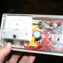
Step 6: The Final Product
Here are some pics.
- Green LED indicates power input is available
- 2 x red LED's showing 5V out and Adj out is available
- ON/OFF switch
- Switch to have the voltmeter measure the 5V output or adjustable, handy
- POT to adjust the variable output voltage.


