

Introduction: Big, Auto Dim, Room Clock (using Arduino and WS2811)


First Hello instructables.
This is my first contact with :
- Instructables
- Arduino
- Programmable LED's
So please don't trow rocks at me for noobish mistakes.
Keeping that in mind I'm waiting to read your comments with grate interest and I'm open to any suggestion
Features :
- big digits ( each digit is approximately the size of a A4 paper).
- slim in order to fit in a photo frame (a big one).
- auto dim the light depending on the light in the room.
- dedicated DST button.
Step 1: Prerequisites


Things I used for this project :
Electronics :
- Arduino nano V3.0 (sadly since I can't afford an original arduino I used a chinese clone, for showing my support I donated 2.9 $ to arduino) - 2.9$ on ebay
Digital Light Intensity Sensor Module Photo Resistor for Arduino - 0.99$ on ebay
DS3231 AT24C32 IIC Module Precision Real Time Clock Quare Memory for Arduino - 0.99$ on ebay
DC-DC Buck Converter Step Down Module LM2596 Power Output 1.23V-30V - 0.90$ on ebay
4m WS2811 led strip 30 leds/m - 12 $ on aliexpress (1 WS2811 IC control 3 LED Chip)
Total cost of electronics : 17.78 $ (without arduino donation)
Miscellaneous :
Heat Shrink Tubing - 7.99$ ebay (assortment, it total 33m)
20 pcs 5 x 7 cm prototype pcb - 3$ ebay
3 pcs Micro Switch - 1$ locally bought
Solder - 1$ locally bought
- Flux - 1$ locally bought
- UTP cable (individual wires used for various connections)
- LCD font (http://www.dafont.com/lcd-lcd-mono.font) - free
- Cardboard - free loacal supermarket
Polystyrene board - 1.50$ locally bought
Various tools.
Step 2: Preparing - Digit Template

- download and install LCD font (http://www.dafont.com/lcd-lcd-mono.font
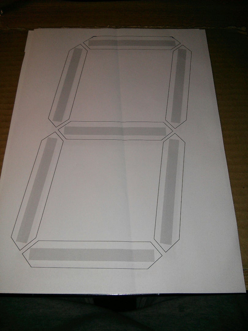
- open word or similar editor and make a template similar to the image (first img)
- font size ~800,
- white font color black outline,
- gray boxes where led strip fits
- Print and cut the gray strips with a exacto knife (second img)
Step 3: Preparing - Cut Cardboard and Led Strip

Using the digit template cut the cardboard to size (don't forget to leave space for the dots between hours and minutes)
If your LED strips came with connectors at each end (like mine did) desolder the connector and cut them in sets of 3.
Step 4: Stick the LED Strips


Using the template stick the LED strip on the cardboard.
It's not mandatory but I used a pencil to mark where the LED strips should be placed, this way I got to see the final form before attaching the LED's. It was a good thing since this is how I noticed I left two much space for those dots in the middle, as a result I had stuck the LED strips a little closer.
Step 5: Solder LED Strips


Now starts a long soldering session.
Solder the LED strips in order to form a continues strip.
Notice the order in which to solder the strips in the picture.
For the middle dots I used a single LED strip and covered the middle LED with duct tape.
I used the following color code
- Blue for ground
- Green for data
- Red for Vcc (12v)
Step 6: Wire Arduino on Breadbord


I tried doing a sketch in fritzing but I can't find all the parts :( , Sorry
So here is a list with all the connections and another picture with the setup on a breadboard
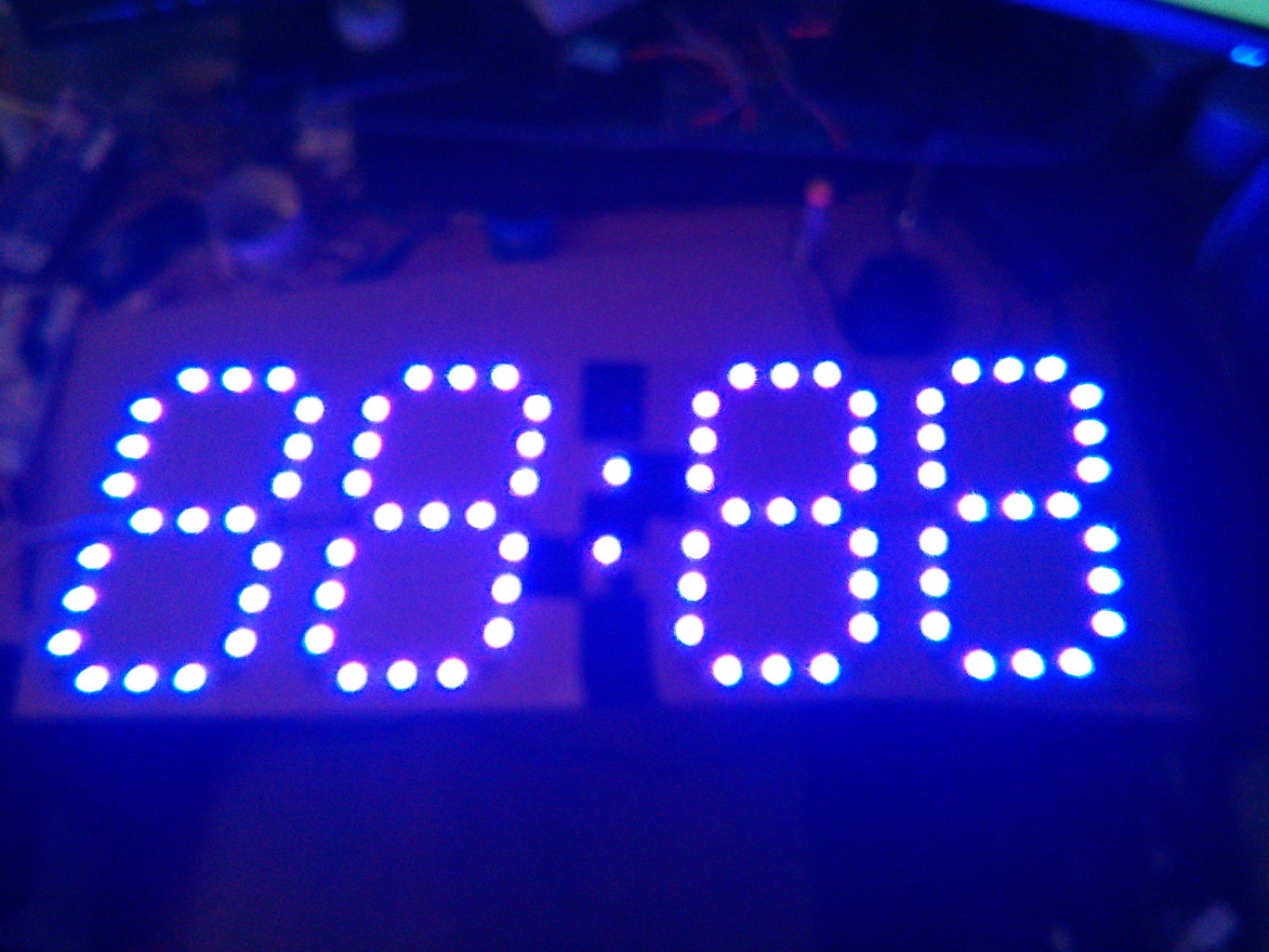
Step 7: Test LED's

Before loading this sketch (for which I assume no credit) don't forget to add FastLED library.
If everything went OK the LED's should cycle trough colors. If you have any problems first check your soldered points.
Attachments

Step 8: Program the Clock
After struggling a little I managed to get a working clock that covers all my needs. I'm sure there is room for improvement.
The code is very commented, if you have any questions please feel free to ask. Also if you have any suggestions, please do tell.
All debugging messages are commented as well.
In order to change the color used you must modify the variable at line 22 ( int ledColor = 0x0000FF; // Color used (in hex)). You can find a list of colors at the bottom of this page: https://github.com/FastLED/FastLED/wiki/Pixel-refe...
If you have problems downloading the code file from instructables here is a mirror : http://bit.ly/1Qjtgg0
Step 9: Make Digits Form Using Polystyrene


Cut each segment in the template printed at the beginning.
Form each digit in the polystyrene using a exacto knife (very hard) or a Hot Wire Cutter.
You can see how I made mine in the pictures.
If you don't have a guitar string you can use just about any thin STEEL wire.
In order to power the Hot Wire Cutter I used the 12v LED power supply.
Also there is a picture with a cut digit. (sorry I forgot to take pictures in the process).
Step 10: Glue Digits and Adding Diffuser

After cutting all 4 digits and the dots glue all of them on the cardboard with the LED strips. (for this process I used
double sided adhesive tape).
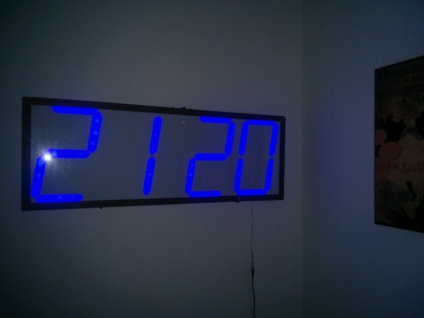
In order to diffuse the LED light I used 2 paper sheets on top of the polystyrene. For convenience and aesthetics I used a single A2 size paper folded in two.
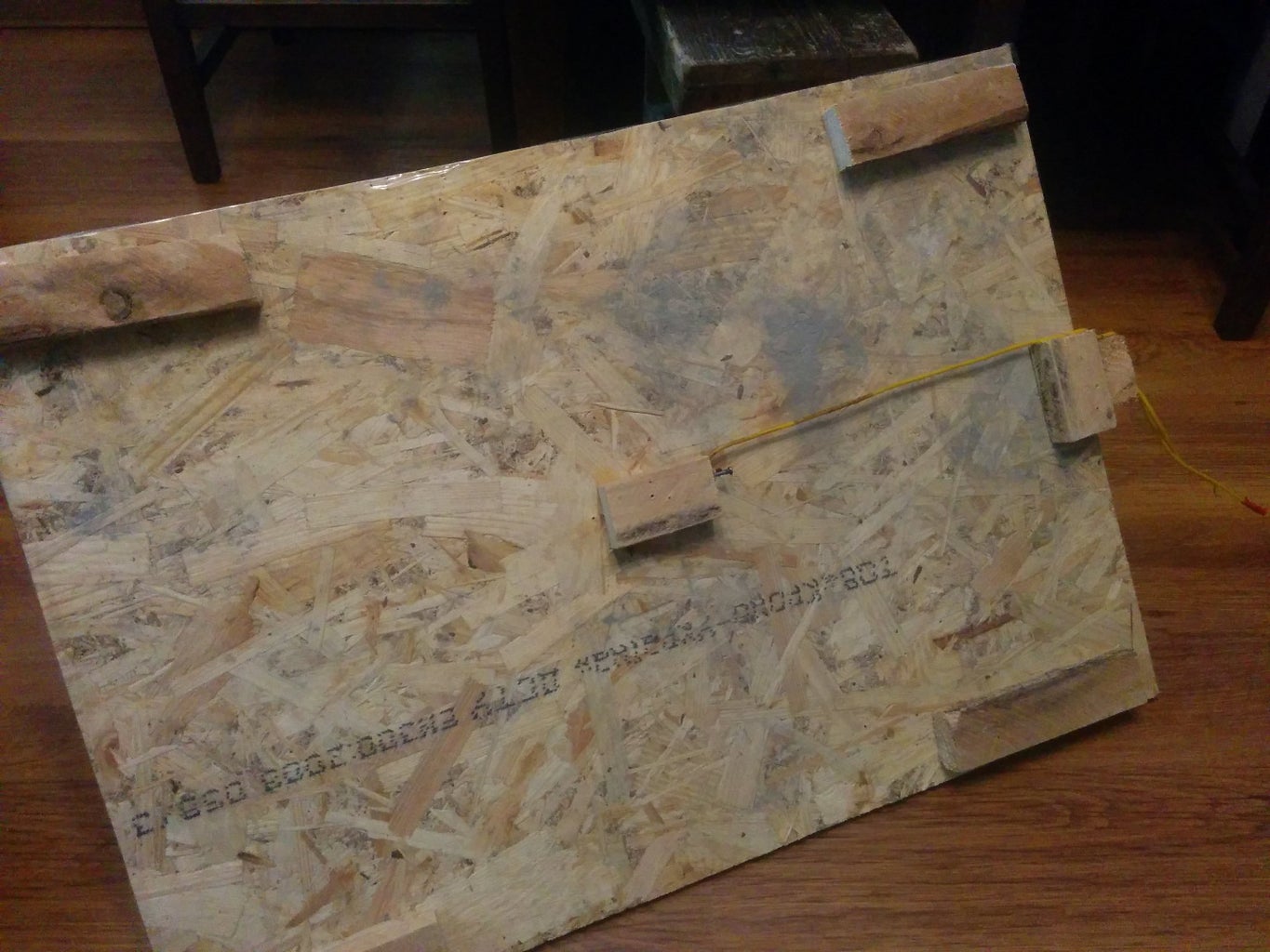
Also for finishing touches I've put the entire assembly in a large picture frame.

Second Prize in the
Time Contest


