

Introduction: Advanced 3D Printing Class: Bike Fender Part 2: Using Parameters


In this lesson, we will complete the first iteration of our design.
Design is an iterative process. It's important to remember that no design is finished on the first try. Keeping this in mind will free you up to work through the first version quickly, and to experiment without stressing about whether the design is perfect. Mistakes and failures are an essential part of the process no matter how advanced your skills are.
We're also going to start using parameters to control our design and keep dimensions consistent throughout.
This class aims to help you develop the skills you need to make whatever you want. We're using the bike fender as an example project to teach you skills and tools that are useful for lots of different things.
Take the skills taught here, and make any project you like.
Step 1: What Are Parameters?
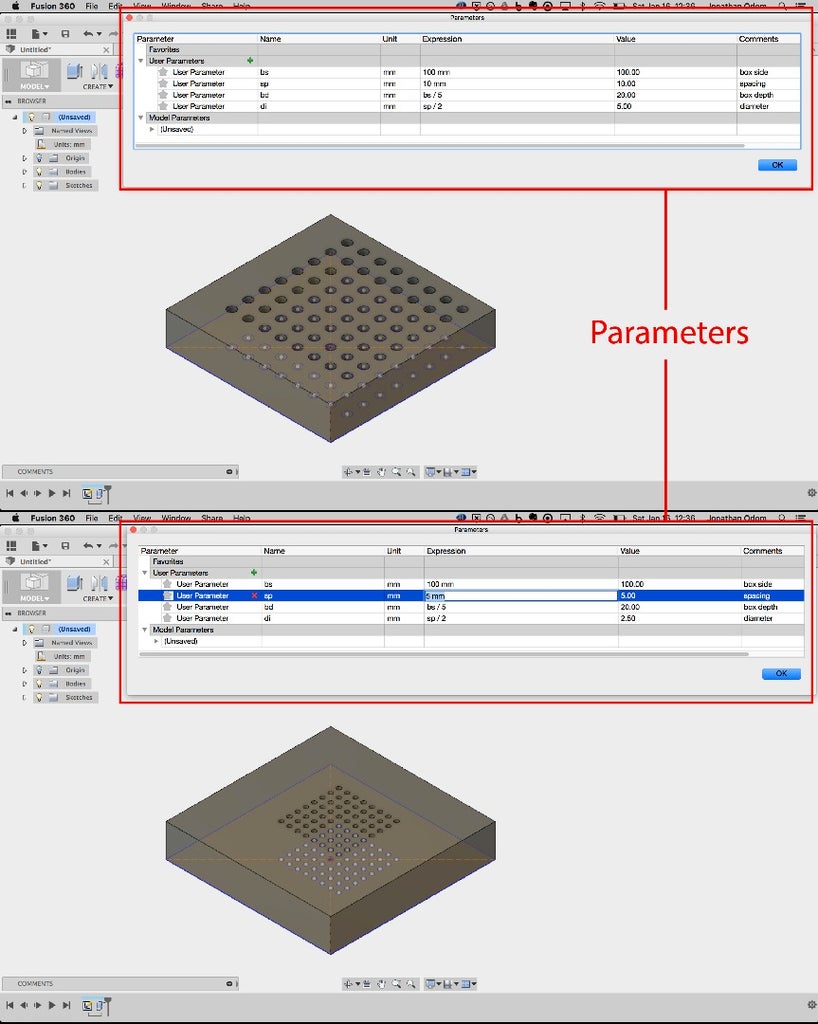
Parametric Modeling is the process of creating a 3D object through the use of parameters. This method is usually mixed with direct modeling to some degree, but objects can also be designed exclusively through parameters. Parametric modeling can be done using any kind of 3D geometry.
In Fusion 360 or Solidworks, parameters can be as simple as a variable representing the diameter of a hole in an object. Using a global parameter allows the user to change the value and have this hole diameter change in every place it occurs in a model.
Step 2: Correct Mistakes

The seat post model had a mistake: the diameter was too large because I didn’t check that the calipers were zeroed before I measured it. They were zeroed at around 5mm instead of 0mm, so my measurement was 5mm too large. Remember, measure twice, 3D Print once!
To Fix this mistake, I create a sketch on the bottom of the seat post, make a circle about the center point that’s 26mm (the correct diameter), then extrude this profile stopping at the end of the seat post.
Step 3: Creating Base Mass Using Parameters
In the same way I started my design by sketching the profile of the fender on paper, I’ll start the 3D model by creating a 2D drawing of the profile.

Create a basic side profile of the fender

Create > Extrude (symmetric)
To create the side profile of the fender, I start by projecting the seat post using the Project tool.
Using my sketch as a guide, I decide to go with 45mm for the depth of the clamp.
Next, I create a parameter for the overall thickness of the model. I went with 6mm in the first iteration, and it felt right in the test print. I use the thickness parameter for the sides of the clamp next to the seat post.
To create the profile of the end of the fender, I mirror a line that represents the slope of the saddle on the left. I think the shape of the fender responding to the shape of the saddle will look good.
To get the length of the fender, I draw a vertical line at the end of the saddle, then mirror it about the center of the drawing. It’s always a good idea to design using whole numbers where possible, so I offset a perpendicular line at the top corner by 300mm- it’s close enough to the length of the saddle that you won’t notice it’s slightly shorter.
Next, I use the trim and extend tools to clean up the drawing.
With my profile worked out, I use the extrude tool to make the base mass of my model. I choose Symmetrical for the direction and New Component for the operation. 85mm looks like a good number for the extents parameter.
Step 4: Refining Mass With Split Body Tool
With the mass in place, it’s time to start adjusting the form. What I’m trying to achieve here is to slim up the shape of the fender while keeping the form as simple as possible. Continuing with sharp edges, I’ll create planes and sketches that will let me split and cut the model, getting me closer to a form that looks good and isn’t bulky.

Extend profile lines

Draw new clamp profile
First, I create a sketch on the side of the mass and extend the profile lines. I’ll use these as guides later. Next, I create a sketch on the bottom of the clamp piece. I project the seat post profile, then offset the circle using my “t” thickness parameter. This will serve as the clamp feature.
I project the end point of the upper line from the previous sketch because I think this might be a good place to taper the clamp feature from. I draw a line from this point to the tangent point of the outer circle and mirror this line about a center line. This angle looks awkward to me, so a create new lines from the end points of the bottom of the sketch. These give me a more graceful shape.
Extrude new bottom profile

Construct > Plane Through Three Points

Create cutting planes on both sides
Modify > Split Body
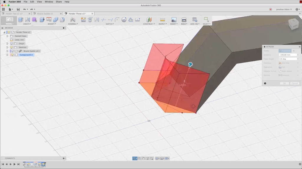
I extrude this profile to cut the original mass. I have to turn off the Bicycle Saddle component so the extrusion doesn’t cut this too.
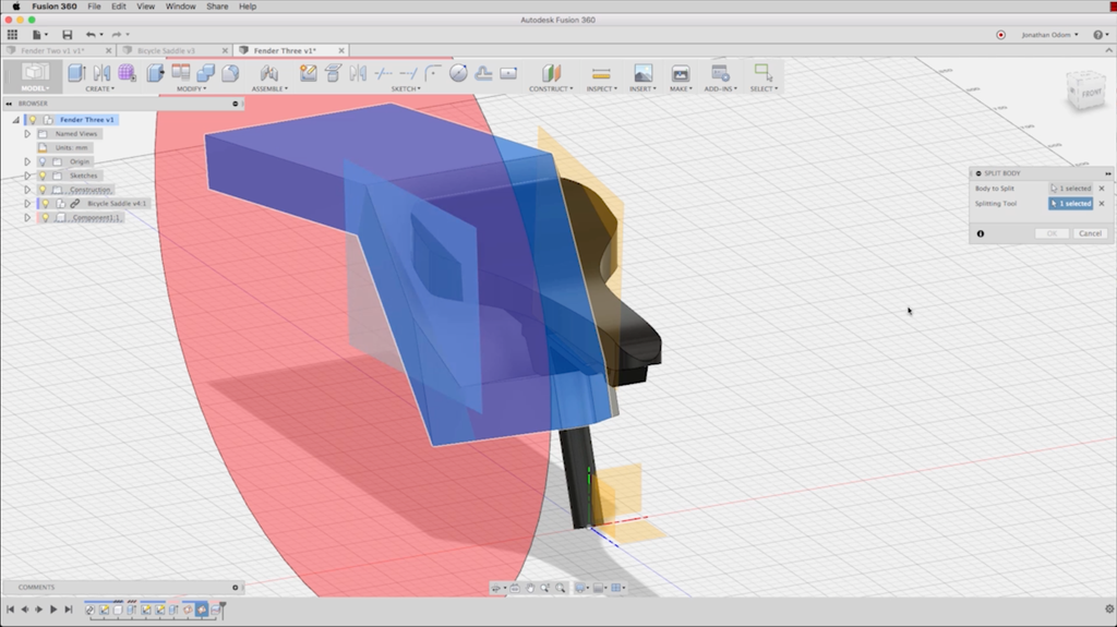
The form isn’t quite finished yet- it still looks too bulky to me, and I don’t like the extra facet created by the last cutting operation. I choose Plane from 3 Points in the Construct menu to create a plane that I’ll use to split the mass, then repeat the same plane on the opposite side.
I then go to Split Body in the Modify menu and split the mass using these two new planes. The result has a better profile than the previous version.

Step 5: Design for Build Envelope
Before I go any further, I need to be certain of one thing: my parts have to fit within the printer’s build envelope!
My fender obviously won’t fit whole, so I need to design it in multiple parts that will connect after they’re printed. Before I start dialing in my design I need to make decisions about where the seams will be between these parts. My build envelope is 230MM X 150mm X 140mm, so my seams will need to take these measurements into account.

Construct > Create Plane Through Three Points

Construct > Offset Plane
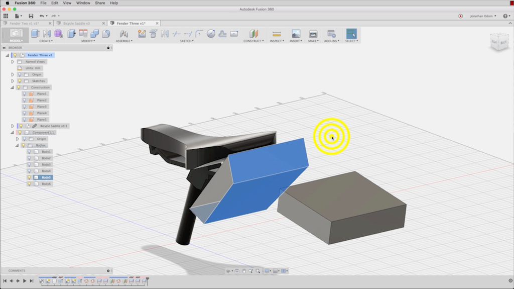
The two obvious places to make seams are (1) along the top plane of the clamp element, and (2) at the elbow where the vertical part and the end part meet. The tail end is too long to fit on the printer bed whole, so I create another cutting plane at about half-way down the length.

Modify > Split Body
I use the Split Body Tool under Modify in the menu again to split the mass along each of the cutting planes.
{
    "id": "quiz-1",
    "question": "What does the Split Body tool do?",
    "answers": [
        {
            "title": "Trims a line drawn on a body",
            "correct": false
        },
        {
            "title": "Cuts a body using a slected face or construciton plane",
            "correct": true
        },
 	{
            "title": "Cuts a body along a selected edge",
            "correct": false
        }
    ],
    "correctNotice": "You got it!",
    "incorrectNotice": "Nope!"
}
Step 6: Shells + Walls
With my basic form in place and my parts sliced to fit the printer bed, I continue to refine the form to fit my idea. My bike fender needs to have a cupped shape that will direct any splashing mud / water back towards the ground. To create this shape, I'm going to turn the solid masses into hollow shells.
Select faces

Modify > Shell
First, I create shells based on the solid bodies that I split previously. I select the 3 under-side faces of the body, then I click the Shell tool under Modify. For the thickness, I use my “t” parameter. I repeat this operation with the two pieces that make up the fender’s end.
Step 7: Create Walls on the Clamp Part
As I look at the model, I realize that the underside of the clamp has some weird geometry. The thickness of the wall gets thinner as a result of my earlier extrusion operation. I’m going to need to create this cut using another tool to make sure my thickness stays consistent.

Redo bottom part- start with extruding circle profile

Select faces for shell operation

Modify > Shell
I undo the Extrude command and create another sketch to extrude the hole for the seat post.
I know I want a consistent shell using my thickness parameter, so I just select the three planes that I want to be cut out, and use the Shell tool to create the main walls.

Create profile on upper part

Create profile on lower part, offset centerline by "t/2"
Now I need to create the wall that joins to the end of the vertical part.
I create a profile sketch on the end of the vertical part, then project the edges of the clamp part.
I want to create a mass that starts at this profile and ends at the bend on the bottom of the clamp, so I create another sketch on this face, draw a center line, and offset lines on either side using “t/2” as the dimension for the offset. This will ensure that the model behaves properly if I want to change the thickness parameter later.

Create > Loft

Select two profiles
With my two profiles in place, I use the Loft tool in the Create menu. This tool takes two profiles in different planes and creates a mass between them. The loft tool is very powerful and can be used to create all kinds of geometry. I use the default Join operation to create a single body for the whole clamp piece.

Done!
{
    "id": "quiz-1",
    "question": "Which of the following is true about the Extrude and Loft tools?",
    "answers": [
        {
            "title": "Extrude pulls a single profile in a single direction.",
            "correct": true
        },
        {
            "title": "Loft pulls a single profile in a single direction.",
            "correct": false
        },
        {
            "title": "Loft creates a solid form by connecting two or more profiles.",
            "correct": true
        }
    ],
    "correctNotice": "You got it!",
    "incorrectNotice": "Nope!"
}
Step 8: Recap
In this lesson, we went deep into the iterative process of design. We used Parameters to control geometry, considered the build-envelope of our 3D Printer as a design factor, and got into the nitty gritty details of multi-part assemblies.
Here are some big ideas to take with you:

Measure twice, model once!
In the beginning of this lesson, I corrected a mistake I made in the first measurements I took. Remember to take your time when you measure and avoid wasting time!

Use Parameters
Parameters are a great way to save time and control a design. You can use them for something as simple as the thickness parameter we covered in this lesson, or if you've savvy you can get sophisticated with functions and formulas.
Split Bodies
The Split Body tool lets you slice through bodies using construction planes.


