

Introduction: Bike Better With an LED Cadence Meter


I love to bike. You might say I'm an amateur (I only own one pair of spandex shorts), but I'm always looking for new ways to improve. Recently I was talking to a more experienced friend, who introduced me to the idea of cadence.
He explained that cadence is how fast you spin the pedals on your bike. Having the right cadence helps conserve energy and reduce muscle strain, so you can ride faster for longer without getting tired.
I did some research and discovered that most amateur cyclists pedal too slowly, pushing hard in high gears and wasting energy. Shifting down and increasing your cadence uses a different set of muscles and makes your biking more efficient.
I wanted an easy, intuitive way to keep track of my cadence, so I would know exactly how fast to pedal and which gear to choose. This project was the result.
Step 1: Research, and Some More About Cadence

Cadence is measured in rotations per minute (rpm). In my research, I found that the ideal cadence for most people falls in the range of 85-95 rpm. I used my watch to conduct some very scientific tests and found that that range worked well for me.
Instead of a stopwatch, advanced cyclists use fancy cycling computers to track cadence and other data while riding. But, like watches, they tend be expensive and hard to read while riding. Even dedicated cadence meters use the same grey, calculator-style numerical display. I wanted more than just a number. I wanted something that I could understand at a glance, and that would actively help me interpret the data.
Step 2: The Plan


I decided to make a meter with no numbers at all. Instead, I chose to use LEDs. The green LED in the middle represents the ideal target range: 85-95 rpm. On either side are yellow and the red LEDs, meaning the cadence is too high or too low. I figured this would let me glance at it quickly while I was riding and adjust without having to think too much.
For the sensor, I decided to use a magnet attached to the crank arm and a hall effect sensor to detect when it passed by. An Arduino would control everything.
The form was based on what I thought looked nice and the limits of my materials and tools, as well as what I had to fit inside.
Step 3: Materials

Sensor
Magnet
10K Resistor
100nF capacitor
4.7nF capacitor (optional)
1/8" stereo jack (example)
Round breadboard
Thin sheet plastic
Velcro
Note: these electronic parts are based on the specific hall effect sensor that I used, and the circuit I found in its datasheet. A different sensor or even a reed switch would work fine.
Meter
Arduino Teensy (I used the 2.0)
5 x 5mm LED (1 green, 2 yellow, 2 red)
SPST slide switch
DC power jack
Breadboard
1/8" sheet acrylic, black and clear
Wiring/Other
DC power plug
1/8" stereo plug
Wires (I used 22 gauge)
Zip ties
It's hard to put a price on this project. I already owned a lot of the electronics, and I didn't buy everything new (most of the acrylic was scrap, for example). I definitely spent more money than I needed to, because nothing works right the first time, and I bought a lot of parts locally. I would recommend planning out the details more thoroughly than I did and ordering everything at once online to minimize the cost.
Step 4: Making the Sensor


The hall effect sensor I used required a circuit with a resistor and at least one capacitor (it's on page seven of the datasheet. I found that leaving out the 4.7nF capacitor didn't affect the sensor's performance). It had three terminals: V0, data, and ground. I used a stereo plug for to connect it to the Arduino, because it has three terminals and is easy to get. I soldered everything to a tiny round circuit board from Radioshack.
I made the sensor enclosure from a sheet of thin frosted plastic, cut carefully with an exacto knife and a circle cutter and held together with Krazy Glue. Make sure to include a place to attach a zip-tie, so that the sensor can be attached to the frame.
The other half of the sensor is just a magnet and some adhesive velcro to attach it to the crank shaft. (I used "industrial strength" velcro. I don't know what that means, but it's holding up well so far).
Step 5: Laser Cut and Epoxy

The enclosure was made from 1/8" black and clear acrylic, cut out in slices and epoxied together in a stack. The file (attached) includes holes for power and data plugs and a switch in the back.
I don't have a picture of the epoxying process, but it's pretty straightforward. Mix the epoxy (it comes in two parts), apply it to each layer with a brush or stick, make sure it doesn't move, and let it dry. I assembled it in two parts: top and bottom. This let me finalize the circuitry inside before attaching the assembled top last.
Contest note: I was lucky enough to be able to use a laser cutter at school to make the enclosure. I have submitted this Instructable to the Epilog contest, in the hope that I might be able to make projects like this at home, with the control and room for creativity that having my own laser cutter would allow. Votes are greatly appreciated!

Step 6: The Electronics


Soldering time! I put the circuit together by cutting up a pre-made perf board and using it as a base to solder everything together. I used an Arduino Teensy for the controller because it fit well inside the box.
Getting the LEDs to fit correctly was the hardest part. I started by sticking them in the top that I had assembled so that they were spaced correctly, then matching the position of the leads to the holes in the PCB. Next I soldered a single LED in at a the height that I thought would work, and adjusted it by trial and error until it fit so that it was pressed into the hole, but I could still close the box. Then I soldered the rest of the LEDs in, matching the height of the first one.
I did as much as I could outside of the box—everything but the switch and plugs. Those have to be installed before they're soldered in. Getting everything to fit was tricky, but it just barely made it! I learned a lot from this part, most importantly that having a solid plan (I didn't) makes things much easier.
I would recommend testing sample code along the way to make sure everything's connected correctly at each step
Step 7: The Code

This code reads when the magnet passes the sensor and keeps a running average of the time between pedal passes. It uses this information to calculate the rotations per minute.
To output to the LEDs, it uses a function to calculate the brightness of each LED based on the rpm value. This creates a smooth fading effect between the LEDs as the values change.
The best way to read from the sensor would have been with interrupts, but I ran into a problem where the values from the sensor weren't high enough to register with the Arduino as digital signals. So I had to use the analog sensor values.
This is not the most elegant code, but it works and is currently locked inside a box on my bike, so I'm posting it as is. Suggestions and changes are welcome.
#define ARRAY_SIZE 3  //The number of values to keep in the running average
#define TIMEOUT 1500  //Max time without input before turning off LEDs
#define FADE_INCREMENT .1  //Controls the fading speed--adjust with trial and error
#define LED_CONSTANT -20 //Used in the brightness fading equation
//RPM targets for each LED:
#define RED_1_TARGET 45
#define YELLOW_1_TARGET 68
#define GREEN_TARGET 90
#define YELLOW_2_TARGET 113
#define RED_2_TARGET 135

/**PORT SETUP**/
const int magnetSensor = A7;  //Change this for your arduino
const int red1 = 12;
const int yellow1 = 10;
const int green = 9;
const int yellow2 = 5;
const int red2 = 4;
const int ledPin = 11;
bool magnetOn = false;
bool prevMagOn = false;
bool primed = false;
bool arrayEmpty = false;
float times[ARRAY_SIZE];  //array to hold values for the running average
float startTime = millis();
int rpm = 0;
bool pedaling = false;
int targetR1;
int targetY1;
int targetG;
int targetR2;
int targetY2;
float r1;
float y1;
float g;
float y2;
float r2;

//add a new value to the array, moving the rest back one space and removing the oldest
void updateTimes(float newValue)
{
  for(int i = 0; i < ARRAY_SIZE-1; i++)  {
    times[i] = times[i+1];
  }
  times[ARRAY_SIZE-1] = newValue;
}

//returns an average of the values in the array
int avgArray(float values[])  {
  int total = 0;
  int counted = ARRAY_SIZE;
  for(int i = 0; i < ARRAY_SIZE; i++)  {
    total = total + values[i];
    if(values[i] == 0)
      counted--;
  }
  return(total/counted);
}

//for debugging
void printValues()  {
  for(int i = 0; i < ARRAY_SIZE - 1; i++)  {
    Serial.print(times[i]);
    Serial.print(", ");
  }
  Serial.println(times[ARRAY_SIZE -1]);
}

//clear the array
void clearTimes()  {
  for(int i = 0; i < ARRAY_SIZE; i++)
    times[i] = 0;
}

//check if the array is full
void checkFullArray()  {
  arrayEmpty = true;
  for(int i = 0; i < ARRAY_SIZE; i++)  {
    if(times[i] != 0)
      arrayEmpty = false;
  }
}

//use a function to calculate the brightness of a given led based on a target
int calculateLED(int target)  {
  if (rpm <= 0)
    return 0;
  return int(LED_CONSTANT*abs(target-rpm)+255);
}

void setup()  {
  pinMode(red1, OUTPUT);
  pinMode(yellow1, OUTPUT);
  pinMode(green, OUTPUT);
  pinMode(yellow2, OUTPUT);
  pinMode(red2, OUTPUT);
  Serial.begin(9600);
}

void loop()  {
  //Read from the hall effect sensor (using analog values, unfortunately)
  int magnetState = analogRead(magnetSensor);
  Serial.println(magnetState);
  if(magnetState > 60)  {
    magnetOn = false;
  }
  else  {
    magnetOn = true;
  }
  if(!magnetOn && prevMagOn)  {
    primed = true;
  }
  //timeout
  if(millis()-startTime > TIMEOUT) {
    clearTimes();
    pedaling = false;
  }
  if(magnetOn && !prevMagOn && primed)  {  //if magnet passes sensor once
    float currentTime = millis();
    float changeTime = (currentTime - startTime);  //record the time since the last pedal
    startTime = millis();
    if(pedaling)  //if there has been pedaling since the last timeout
      updateTimes(changeTime);  //add the time to the running average array
    primed = false;
    pedaling = true;
  }

  //mostly for debugging, this blinks the built-in LED whenever the magnet passes the sensor
  if(magnetOn)
    digitalWrite(ledPin, HIGH);
  else
    digitalWrite(ledPin, LOW);
  prevMagOn = magnetOn;
  checkFullArray();
  float gap = avgArray(times);
  if(arrayEmpty)  {
    rpm = 0;
  }
  else
    rpm = 60000/gap;  //turn millisecond gap value into rpm
  //light the lowest red LED when the first pedal stroke is recorded, since there isn't enough data to calculate rpm
  if(pedaling && rpm == 0)
    rpm = 40;

  /******LED OUTPUT*****/
  //calculate values
  targetR1 = calculateLED(RED_1_TARGET);
  targetY1 = calculateLED(YELLOW_1_TARGET);
  targetG = calculateLED(GREEN_TARGET);
  targetY2 = calculateLED(YELLOW_2_TARGET);
  targetR2 = calculateLED(RED_2_TARGET);
  //Normalize negative values to zero (these should really be in an array...)
  if(targetR1 < 0)
    targetR1 = 0;
  if(targetY1 < 0)
    targetY1 = 0;
  if(targetG < 0)
    targetG = 0;
  if(targetY2 < 0)
    targetY2 = 0;
  if(targetR2 < 0)
    targetR2 = 0;

  //fade to value
  if (r1 < targetR1)
    r1 += FADE_INCREMENT;
  if (r1 > targetR1)
    r1 -= FADE_INCREMENT;
  if (y1 < targetY1)
    y1 += FADE_INCREMENT;
  if (y1 > targetY1)
    y1 -= FADE_INCREMENT;
  if (g < targetG)
    g += FADE_INCREMENT;
  if (g > targetG)
    g -= FADE_INCREMENT;
  if (y2 < targetY2)
    y2 += FADE_INCREMENT;
  if (y2 > targetY2)
    y2 -= FADE_INCREMENT;
  if (r2 < targetR2)
    r2 += FADE_INCREMENT;
  if (r2 > targetR2)
    r2 -= FADE_INCREMENT;

  //output to LEDs
  analogWrite(red1, r1);
  analogWrite(yellow1, y1);
  analogWrite(green, g);
  analogWrite(yellow2, y2);
  analogWrite(red2, r2);
}
Attachments
Step 8: Power and Wiring


Because of the power demands of the Arduino, this runs on three AAA batteries. In the future I would like to make it pedal-powered, but that's a project for another day.
To attach the battery holder to the bike, I used an old mounting bracket for a lock that I had in the garage. I Dremeled and sanded the end of it flat and glued on the battery holder (I used Duco Cement because I was out of epoxy). Then I could attach the battery holder to the bike frame by fastening the mount with the two bolts it came with.
To let the sensor communicate with the meter, you need three wires connected to a stereo AUX plug at either end long enough to run from the sensor to the meter.
For power, you need two wires soldered to a DC plug at one end and to the battery pack at the other long enough to reach from the battery holder to the meter.
I used multicolored 22 gauge stranded wire and twisted it together myself because it was easy to keep track of the connections and I liked the way it looked. There are many other ways to do it that will be both subtler and easier on your hands.
Step 9: Handlebar Mount and Finishing Touches

When you're satisfied that everything is working, glue the top on the box. (Confession: I used Elmer's glue for this last part because I thought I might want to change the code and there are no second chances with epoxy).
To clean up the outside, I sanded it down until it was fairly seamless and finished it with a dremel polishing bit. I actually ended up rubbing a little black dye onto the sanded edges to make them as dark as the smooth top.
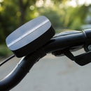
To make the handlebar mount, I cut the bottom off a cheap bike bell and epoxied it to the base of the meter. It slips around the handlebars and tightens with a screw (see the next step for another view).
The stereo and DC jacks come with rings that screw onto the outside of the enclosure to secure them and give everything a more finished look.
Step 10: Installation

Now it's ready to be attached to the bike! Velcro the magnet to the crank shaft and zip tie the sensor to the frame. Mount the meter to the handlebars and tighten it. Screw the battery holder mount onto the frame in a good place. Plug the wires in and zip tie them to the frame so they're out of the way, allowing room to turn the handlebars. Switch it on, cross your fingers, and it should light up when you spin the pedals! If it doesn't work, the sensor is probably not positioned close enough to the magnet or the batteries are dead.
Step 11: Ride!

That's it! To use this most effectively, choose a speed you want to ride at and start pedaling. If the LEDs to the left of the green light are illuminated, shift down and pedal faster while maintaining that speed. Do the opposite if you're pedaling too fast. You should be able to find a good rhythm within the green zone that lets you keep pedaling with minimal effort. If you start to stray away, the lights will let you know. Keep in mind that the meter is just a general guide, and it's fine to vary your cadence a bit.
I wasn't sure what to expect from this project, but this little meter has changed the way I ride my bike. I used to fight against the gears and wear myself out too quickly. Now I can glance at my handlebars, change gears, and pedal more efficiently. I hope it can help you too. Good luck!

Participated in the
Epilog Challenge VI

Participated in the
Great Outdoors Contest

Participated in the
Battery Powered Contest

Participated in the
Wheels Contest


