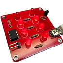
Introduction: Binary Thermometer USB Powered
Assembly instructions for the Binary Thermometer Kit I designed.
You can purchase one at:
http://www.etsy.com/listing/122729791/
You can purchase one at:
http://www.etsy.com/listing/122729791/
Step 1: Get Your Iron Hot
I use Lead-Free solder with my iron set to 320 degrees Celsius. It is a good idea to keep a wet cellulose sponge handy to clean your iron tip occasionally. You will not need a fancy temperature controlled iron, but they do make soldering more of a pleasure.
Step 2: The Spread
Layout all your parts to make sure you have everything you need. If you have all that is shown in the picture, you should be ready to go!
Step 3: Lights
First we will populate the eight LED's onto the board. Please notice that each LED has a flat side. This should match the flat side on the white outlines printed on the board. Once the LED's are in place, check again to make sure they are oriented properly prior to soldering. Also, be sure they are flush with the board as well.
You should have nice chocolate kiss shaped solder joints. If not, do not worry, that will come with practice. Be sure to heat the joint (not the solder) and let the solder flow into the circuit board hole filling the void and bonding to the LED wires.
You may use a set of wire trimmers to clip off the excess leads. I got these clippers in the craft section of Wal-Mart and they work great for cutting wires nearly flat to the board.
Step 4: Four and No More
Now we can solder our four resistors. Bend the leads right at the resistors ends and place them in the marked holes, flush with the board. You can bend them a bit so they stay in place while you solder. Cut the excess leads flush just like the LED's.
Step 5: Z Power
We are about half-way there!
Next we solder on the USB connector. The leads are small, but we only have to solder the two outer ones. Be sure to not bridge any of the leads with stray solder.
You should also solder the USB connector tabs on the top and bottom of the board for a good mechanical connection.
Next, solder on the jumpers for the Celsius/ Fahrenheit switch. If you want to power the kit with an external 5 volt supply, you can solder on that jumper as well. They are both labeled on the board.
Step 6: The Brain
We need a computer to coordinate the temperature measurements and LED lighting. The 8-pin black microcontroller does this for us. Be sure to orient it properly on the board. The dot on top of the chip should match up with the tab on the board's white outline. The pictures show this clearly.
Step 7: 98.6
Let's solder the temperature sensor. It is accurate to about 1 Degree Celsius. Oriented it with the flat side matching the board. You can bend it flat if you would like. Do not heat it anymore than you must when soldering to prevent damage.
Step 8: Voila!
Plug a powered USB cable in and with the board light up!
All of the LED's will light first as a test. If all the LED's do not light, check your orientations.
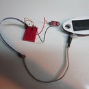
The clock will give the temperature first in Celsius and then in Fahrenheit. Below it is reading 68 degrees.
If you would like to read the clock in Celsius, just place a jumper across the "C/F Select" jumper pins.
Congratulations and enjoy your thermometer!


