

Introduction: Bionic Iron Man Armor (w/ Sound Effects)


CHECK OUT OUR NEW VERSION HERE
In the spirit of the upcoming release of Iron Man 3, we've decided to teach you how to build some killer Stark Industries tech to show off while camping out at the front of the line of the midnight show.
This Instructable will teach you how to build a Repulsor that uses one of our third-generation Muscle Sensors to give you that truly immersive and realistic feel.
I AM IRON MAN!
Simply flex your forearm muscle and hear the repulsor charge up, then relax your forearm to fire (lighting up the LEDs on your palm and playing explosion sound effects). As an added flair for realism, when you turn on the system, J.A.R.V.I.S.'s voice takes you through the boot up and calibration sequence.
About Advancer Technologies
Advancer Technologies is a company devoted to developing innovative game-changing biomechatronic technologies and applied sciences. Additionally, Advancer Technologies promotes all forms of interest and learning into biomechatronic technologies. To help cultivate and educate future great minds and concepts in the field, they frequently post informative instructions on some of their technologies. For more information, please visit www.AdvancerTechnologies.com.
Step 1: Gather the Materials

- (1) Advancer Technologies Muscle Sensor (Note: v3 sensor comes with cables)
- (1) LED Tap Light
- (1) set of Gloves
- (1) +5V Fixed Voltage Regulator
- (1) Arduino MCU (Note: Uno is used in these instructions)
- (1) Adafruit Wave Shield (make sure to get the stackable headers)
- (1) Adafruit Proto Shield
- (1) SD Card
- (1) Small Speaker
- (2) 9V Battery
- Wire
EITHER:
(for the conductive fabric electrode sleeve)
- (1) Underarmer Sleeve
- (1) Stretch Conductive Fabric (sample size will due)
- (1) package of Button Snaps (should have at least 3 sets)
- Needle and Thread
OR:
- (1) bag of EMG Electrodes
You will need the following tools:
- Soldering Iron
- Hammer
- Hot Glue Gun
Step 2: [Repulsor Glove] Disassembling the LED Tap Light
![[Repulsor Glove] Disassembling the LED Tap Light](https://content.instructables.com/FU7/9WEW/HD7U17HJ/FU79WEWHD7U17HJ.jpg?auto=webp&fit=bounds&frame=1&height=1024&width=1024auto=webp&frame=1&height=300)
Start by disassembling the LED Tap Light and remove the circuit board. This should be relatively easy and can be done with only a screwdriver.
Make sure you keep the:
- LED Circuit Board
- LED reflecting plate
Set aside the lens and reflecting plates, you'll need these later on but first we'll work on modifying the circuit board.
Step 3: [Repulsor Glove] Removing the LED Tap Light Button and Wires (Optional)
![[Repulsor Glove] Removing the LED Tap Light Button and Wires (Optional)](https://content.instructables.com/F5Z/V8N1/HD7U17I0/F5ZV8N1HD7U17I0.jpg?auto=webp&fit=bounds&frame=1&height=1024&width=1024auto=webp&frame=1&height=300)
There are a few different ways to do this. I've found the easiest way is to use a soldering iron and a screwdriver.
- Use the soldering iron to reflow the solder and then use a screwdriver to straighten the pins. [You can also do this with a heat gun.]
- Next, pick up the soldering iron again and solder the pins previously connected by the switch to permanently complete the circuit.
Step 4: [Repulsor Glove] Rewiring the LED Tap Light Circuit Board
![[Repulsor Glove] Rewiring the LED Tap Light Circuit Board](https://content.instructables.com/FS0/53KW/HD4VHHAX/FS053KWHD4VHHAX.jpg?auto=webp&fit=bounds&frame=1&height=1024&width=1024auto=webp&frame=1&height=300)
![[Repulsor Glove] Rewiring the LED Tap Light Circuit Board](https://content.instructables.com/FNO/HJ6V/HDOVVY51/FNOHJ6VHDOVVY51.jpg?auto=webp&fit=bounds&frame=1&height=1024&width=1024auto=webp&frame=1&height=300)
- Cut off two lengths of wire and strip and tin 1/8" of the ends of each wire. These are going to connect the LED lights on the glove to the Arduino so make sure to make them long enough to reach where ever you're planning on putting the Arduino board. I'm planning on hiding most of this setup in my Mark V armor forearm gauntlet so I'm using XX inches of wire.
- If your wires aren't twisted together or paired already, I'd go ahead now and twist them together to cut down on clutter. I'm using stereo wires so I won't be twisting mine.
- Now, solder the wires to the board where the wires to the batteries were previously. I've highlighted these in the photos to show you where they were for my specific tap light model.
- Once soldered, connect the wires to a battery to make sure the board lights up. Make sure to pay attention to which is the positive and negative terminal... you could potentially burn out your LEDs if you connect them wrong.
Tip: If you have some thin scrap foam or rubber available, I would recommend cutting out a piece to glue on the back side of the circuit board so the solder points don't scratch your hand every time you put the glove on.
Step 5: [Repulsor Glove] Preparing the Glove for the LED Lights
![[Repulsor Glove] Preparing the Glove for the LED Lights](https://content.instructables.com/FYP/AJUZ/HD4VG6LX/FYPAJUZHD4VG6LX.jpg?auto=webp&fit=bounds&frame=1&height=1024&width=1024auto=webp&frame=1&height=300)
![[Repulsor Glove] Preparing the Glove for the LED Lights](https://content.instructables.com/FGR/4IE4/HDHW52UI/FGR4IE4HDHW52UI.jpg?auto=webp&fit=bounds&frame=1&height=1024&width=1024auto=webp&frame=1&height=300)
- Start by putting on one of the gloves then find the reflecting plate that you set aside earlier and set it on your palm. Make sure to get it in a position that is comfortable for you to close your hand.
- Then, using a permanent marker, trace the nine circle cutouts where the LED lights would usually go (ignore the center hole).
- Next, use an Exacto knife or some other kind of precision cutting tool to cut out the 9 circles you just traced. Make sure to put some kind of hard backing material (e.g. piece of scrap plastic) in the glove to go behind where you are cutting. This will make sure you don't accidentally cut the whole way through the glove instead of just the one side.
Step 6: [Repulsor Glove] Attaching the LED Lights to the Glove
![[Repulsor Glove] Attaching the LED Lights to the Glove](https://content.instructables.com/F79/E96P/HD4VNL3Q/F79E96PHD4VNL3Q.jpg?auto=webp&fit=bounds&frame=1&height=1024&width=1024auto=webp&frame=1&height=300)
![[Repulsor Glove] Attaching the LED Lights to the Glove](https://content.instructables.com/F18/5GRU/HDOW3JT0/F185GRUHDOW3JT0.jpg?auto=webp&fit=bounds&frame=1&height=1024&width=1024auto=webp&frame=1&height=300)
![[Repulsor Glove] Attaching the LED Lights to the Glove](https://content.instructables.com/FGA/NFM4/HDOVVY52/FGANFM4HDOVVY52.jpg?auto=webp&fit=bounds&frame=1&height=1024&width=1024auto=webp&frame=1&height=300)
- If you have a Dremel tool or a sander ready, I'd take a minute to round the corners of the circuit board and take any sharp edges off the board. You don't want the board to cut you when you're taking the glove on and off.
- I would also suggest getting some kind of backing material such as EPA foam (which I'm using) and cut out a section in the shape of your board. This will protect your skin from snagging on the the solder points of the circuit board and make wearing the glove more comfortable.
- If you're using backing material, use a hot glue gun to glue the material to the back of the circuit board.
- Next, turn the glove inside out and use the glue gun to the glue the circuit board to the inside of the glove, making sure the LED lights poke through the holes you cut out earlier. You'll also want to orient the board such that the wire you attached to the board earlier runs down your arm.
Step 7: [Repulsor Glove] Attaching the Reflecting Plate to the Glove
![[Repulsor Glove] Attaching the Reflecting Plate to the Glove](https://content.instructables.com/F7C/UJ9N/HDOW6FMM/F7CUJ9NHDOW6FMM.jpg?auto=webp&fit=bounds&frame=1&height=1024&width=1024auto=webp&frame=1&height=300)
Since the reflecting plate will be slightly offset from the glove, I've use some more scrap EPA foam to create a bezel to fill in this space.
- If you're using a bezel, first use the hot glue gun to attach it to the reflecting plate before gluing both pieces to the glove.
- If you aren't using a bezel, go ahead and glue the reflecting plate to the glove.
Next up we'll make a muscle sensor shield to use with the Wave Shield and our trusty Arduino MCU...
Step 8: [Muscle Sensor Shield] Attaching the Header Pins
![[Muscle Sensor Shield] Attaching the Header Pins](https://content.instructables.com/FWR/H3DH/HDOW3Y7C/FWRH3DHHDOW3Y7C.jpg?auto=webp&fit=bounds&frame=1&height=1024&width=1024auto=webp&frame=1&height=300)
![[Muscle Sensor Shield] Attaching the Header Pins](https://content.instructables.com/FIL/4BCW/HDYZ85GO/FIL4BCWHDYZ85GO.jpg?auto=webp&fit=bounds&frame=1&height=1024&width=1024auto=webp&frame=1&height=300)
![[Muscle Sensor Shield] Attaching the Header Pins](https://content.instructables.com/F9I/GMPT/HFSHSD5G/F9IGMPTHFSHSD5G.jpg?auto=webp&fit=bounds&frame=1&width=1024auto=webp&frame=1&height=300)
We're going to start off by soldering on headers to the bottom side of the Protoboard.
- Break off two six pin sections and two eight pin sections. Push them into the sockets of your Wave Shield.
- Next, line up your Protoboard's holes with the headers and set it down on them.
- Finish this step by soldering all the header pins from the top side of the Protoboard.
Step 9: [Muscle Sensor Shield] Soldering the Muscle Sensor Board
![[Muscle Sensor Shield] Soldering the Muscle Sensor Board](https://content.instructables.com/F06/KKZ0/HE081Q0F/F06KKZ0HE081Q0F.jpg?auto=webp&fit=bounds&frame=1&height=1024&width=1024auto=webp&frame=1&height=300)
![[Muscle Sensor Shield] Soldering the Muscle Sensor Board](https://content.instructables.com/FBN/CLHL/HDYZC7L5/FBNCLHLHDYZC7L5.jpg?auto=webp&fit=bounds&frame=1&height=1024&width=1024auto=webp&frame=1&height=300)
![[Muscle Sensor Shield] Soldering the Muscle Sensor Board](https://content.instructables.com/F90/S5YQ/HE081Q0Z/F90S5YQHE081Q0Z.jpg?auto=webp&fit=bounds&frame=1&height=1024&width=1024auto=webp&frame=1&height=300)
![[Muscle Sensor Shield] Soldering the Muscle Sensor Board](https://content.instructables.com/FT1/P76F/HDYZE07A/FT1P76FHDYZE07A.jpg?auto=webp&fit=bounds&frame=1&height=1024&width=1024auto=webp&frame=1&height=300)
![[Muscle Sensor Shield] Soldering the Muscle Sensor Board](https://content.instructables.com/FBQ/NWWA/HE081Q0Y/FBQNWWAHE081Q0Y.jpg?auto=webp&fit=bounds&frame=1&height=1024&width=1024auto=webp&frame=1&height=300)
![[Muscle Sensor Shield] Soldering the Muscle Sensor Board](https://content.instructables.com/F5I/AS45/HE081Q0X/F5IAS45HE081Q0X.jpg?auto=webp&fit=bounds&frame=1&height=1024&width=1024auto=webp&frame=1&height=300)
![[Muscle Sensor Shield] Soldering the Muscle Sensor Board](https://content.instructables.com/F9L/FD2S/HE07PREH/F9LFD2SHE07PREH.jpg?auto=webp&fit=bounds&frame=1&height=1024&width=1024auto=webp&frame=1&height=300)
- Grab some header pins and snip the top off them and solder them to the board as shown. We're going to use these to prop up the sensor board and take some of the strain of the other pins.
- Grab another set of header pins and solder them to the Muscle Sensor board.
- Solder the Muscle Sensor board to the protoboard. The -Vs pin should be in line with and two pins below the GND strip.
Step 10: [Muscle Sensor Shield] Solder the Switch
![[Muscle Sensor Shield] Solder the Switch](https://content.instructables.com/F7Z/DEIX/HE081Q0W/F7ZDEIXHE081Q0W.jpg?auto=webp&fit=bounds&frame=1&height=1024&width=1024auto=webp&frame=1&height=300)
![[Muscle Sensor Shield] Solder the Switch](https://content.instructables.com/FYD/USCK/HE07PREG/FYDUSCKHE07PREG.jpg?auto=webp&fit=bounds&frame=1&height=1024&width=1024auto=webp&frame=1&height=300)
- Solder the switch as shown. You have to leave a row of pins holes in front of the switch so you have room to access the front middle pins of the switch.
- Clip the pins.
Step 11: [Muscle Sensor Shield] Solder the +5V Regulator
![[Muscle Sensor Shield] Solder the +5V Regulator](https://content.instructables.com/FS1/2WSZ/HE081Q0V/FS12WSZHE081Q0V.jpg?auto=webp&fit=bounds&frame=1&height=1024&width=1024auto=webp&frame=1&height=300)
![[Muscle Sensor Shield] Solder the +5V Regulator](https://content.instructables.com/FJY/NG8Q/HE081Q0S/FJYNG8QHE081Q0S.jpg?auto=webp&fit=bounds&frame=1&height=1024&width=1024auto=webp&frame=1&height=300)
- Solder the +5V regulator, as shown.
- Clip the pins.
Step 12: [Muscle Sensor Shield] Connect the +9V Switch to Vin
![[Muscle Sensor Shield] Connect the +9V Switch to Vin](https://content.instructables.com/F5X/62S5/HE081Q0Q/F5X62S5HE081Q0Q.jpg?auto=webp&fit=bounds&frame=1&height=1024&width=1024auto=webp&frame=1&height=300)
![[Muscle Sensor Shield] Connect the +9V Switch to Vin](https://content.instructables.com/FCN/RMDU/HDYZ85GT/FCNRMDUHDYZ85GT.jpg?auto=webp&fit=bounds&frame=1&height=1024&width=1024auto=webp&frame=1&height=300)
![[Muscle Sensor Shield] Connect the +9V Switch to Vin](https://content.instructables.com/FGN/LJCZ/HDYZJEWS/FGNLJCZHDYZJEWS.jpg?auto=webp&fit=bounds&frame=1&height=1024&width=1024auto=webp&frame=1&height=300)
- Grab some hook up wire and solder one end to the top left pin of the switch (when looking at the bottom of the board).
- Instead of clipping the wire after you solder it in, bend the wire to bridge the gap between the switch pin and the wire pin.
- Solder the other end of the wire to the Vin pin on the protoboard; clip the wire accordingly.
Step 13: [Muscle Sensor Shield] Connect the Muscle Sensor +Vs Pin to +5V
![[Muscle Sensor Shield] Connect the Muscle Sensor +Vs Pin to +5V](https://content.instructables.com/FCM/03MJ/HE07PREC/FCM03MJHE07PREC.jpg?auto=webp&fit=bounds&frame=1&height=1024&width=1024auto=webp&frame=1&height=300)
![[Muscle Sensor Shield] Connect the Muscle Sensor +Vs Pin to +5V](https://content.instructables.com/FHJ/AW89/HDYZ6HVB/FHJAW89HDYZ6HVB.jpg?auto=webp&fit=bounds&frame=1&height=1024&width=1024auto=webp&frame=1&height=300)
- Solder the wire to the pin on the protoboard above the Muscle sensor +Vs pin.
- Instead of clipping the wire after you solder it in, bend the wire to bridge the gap between the +Vs pin and the wire pin.
- Solder the wire bridge so that solder spans the entire gab between the pins.
- Solder the other end of the wire to the 5V power strip on the protoboard; clip the wire accordingly.
Step 14: [Muscle Sensor Shield] Connect the Muscle Sensor GND Pin to GND
![[Muscle Sensor Shield] Connect the Muscle Sensor GND Pin to GND](https://content.instructables.com/F7X/AUSR/HE07PRDV/F7XAUSRHE07PRDV.jpg?auto=webp&fit=bounds&frame=1&height=1024&width=1024auto=webp&frame=1&height=300)
![[Muscle Sensor Shield] Connect the Muscle Sensor GND Pin to GND](https://content.instructables.com/FSR/SHUW/HE07PREB/FSRSHUWHE07PREB.jpg?auto=webp&fit=bounds&frame=1&height=1024&width=1024auto=webp&frame=1&height=300)
![[Muscle Sensor Shield] Connect the Muscle Sensor GND Pin to GND](https://content.instructables.com/FBI/97KC/HDYZ6HVA/FBI97KCHDYZ6HVA.jpg?auto=webp&fit=bounds&frame=1&height=1024&width=1024auto=webp&frame=1&height=300)
- Solder the wire to the pin on the protoboard above the Muscle sensor GND pin.
- Instead of clipping the wire after you solder it in, bend the wire to bridge the gap between the GND pin and the wire pin.
- Solder the wire bridge so that solder spans the entire gab between the pins
- Solder the other end of the wire to the GND power strip on the protoboard; clip the wire accordingly.
Step 15: [Muscle Sensor Shield] Connect the Muscle Sensor -Vs Pin to 5V Regulator GND Pin
![[Muscle Sensor Shield] Connect the Muscle Sensor -Vs Pin to 5V Regulator GND Pin](https://content.instructables.com/FUN/QSL3/HE07PRDW/FUNQSL3HE07PRDW.jpg?auto=webp&fit=bounds&frame=1&height=1024&width=1024auto=webp&frame=1&height=300)
![[Muscle Sensor Shield] Connect the Muscle Sensor -Vs Pin to 5V Regulator GND Pin](https://content.instructables.com/F6P/5BWY/HDYZJEWM/F6P5BWYHDYZJEWM.jpg?auto=webp&fit=bounds&frame=1&height=1024&width=1024auto=webp&frame=1&height=300)
![[Muscle Sensor Shield] Connect the Muscle Sensor -Vs Pin to 5V Regulator GND Pin](https://content.instructables.com/FP3/QYC8/HE07PRDZ/FP3QYC8HE07PRDZ.jpg?auto=webp&fit=bounds&frame=1&height=1024&width=1024auto=webp&frame=1&height=300)
- Solder the wire to the pin on the protoboard above the Muscle sensor -Vs pin.
- Instead of clipping the wire after you solder it in, bend the wire to bridge the gap between the -Vs pin and the wire pin.
- Solder the wire bridge so that solder spans the entire gab between the pins.
- Solder the other end of the wire to the the pin on the protoboard above the voltage regulator GND pin.
- Instead of clipping the wire after you solder it in, bend the wire to bridge the gap between the voltage regulator GND pin and the wire pin.
Step 16: [Muscle Sensor Shield] Connect the Muscle Sensor SIG Pin to Arduino A0 Pin
![[Muscle Sensor Shield] Connect the Muscle Sensor SIG Pin to Arduino A0 Pin](https://content.instructables.com/F42/BE5I/HE07PRDO/F42BE5IHE07PRDO.jpg?auto=webp&fit=bounds&frame=1&height=1024&width=1024auto=webp&frame=1&height=300)
![[Muscle Sensor Shield] Connect the Muscle Sensor SIG Pin to Arduino A0 Pin](https://content.instructables.com/F9O/41YM/HDYZ6ZU2/F9O41YMHDYZ6ZU2.jpg?auto=webp&fit=bounds&frame=1&height=1024&width=1024auto=webp&frame=1&height=300)
![[Muscle Sensor Shield] Connect the Muscle Sensor SIG Pin to Arduino A0 Pin](https://content.instructables.com/FNI/8S4D/HE081Q0L/FNI8S4DHE081Q0L.jpg?auto=webp&fit=bounds&frame=1&height=1024&width=1024auto=webp&frame=1&height=300)
- Solder the wire to the pin on the protoboard above the Muscle sensor SIG pin.
- Instead of clipping the wire after you solder it in, bend the wire to bridge the gap between the SIG pin and the pin the wire is soldered to.
- Solder the wire bridge so that solder spans the entire gab between the pins
- Solder the other end of the wire to the A0 pin on the protoboard; clip the wire if needed.
Step 17: [Muscle Sensor Shield] Connect the Two 9V Battery Clips
![[Muscle Sensor Shield] Connect the Two 9V Battery Clips](https://content.instructables.com/F4L/QIBZ/HDYZJEWC/F4LQIBZHDYZJEWC.jpg?auto=webp&fit=bounds&frame=1&height=1024&width=1024auto=webp&frame=1&height=300)
One of them will be used to power the Arduino and generate the +5V supply for the Muscle sensor, the second will be used to created the virtual ground so that we have a -5V supply for the Muscle sensor.
- Grab the two 9V battery clips and solder them to the protoboard, as shown.
- Clip the wires, if needed.
Step 18: [Muscle Sensor Shield] Connect the First Battery (Positive Lead to Switch)
![[Muscle Sensor Shield] Connect the First Battery (Positive Lead to Switch)](https://content.instructables.com/FE8/GBAO/HDYZ6ZTV/FE8GBAOHDYZ6ZTV.jpg?auto=webp&fit=bounds&frame=1&height=1024&width=1024auto=webp&frame=1&height=300)
![[Muscle Sensor Shield] Connect the First Battery (Positive Lead to Switch)](https://content.instructables.com/F98/Y4PI/HE07PRDJ/F98Y4PIHE07PRDJ.jpg?auto=webp&fit=bounds&frame=1&height=1024&width=1024auto=webp&frame=1&height=300)
![[Muscle Sensor Shield] Connect the First Battery (Positive Lead to Switch)](https://content.instructables.com/FON/MHKF/HDYZJEWJ/FONMHKFHDYZJEWJ.jpg?auto=webp&fit=bounds&frame=1&height=1024&width=1024auto=webp&frame=1&height=300)
![[Muscle Sensor Shield] Connect the First Battery (Positive Lead to Switch)](https://content.instructables.com/FXN/DYFJ/HE07PRDK/FXNDYFJHE07PRDK.jpg?auto=webp&fit=bounds&frame=1&height=1024&width=1024auto=webp&frame=1&height=300)
- Solder the wire to the pin on the protoboard below the first battery positive pin.
- Bend the wire to bridge the gap between the wire pin and the battery's positive pin.
- Solder the wire bridge so that solder spans the entire gab between the pins.
- While looking at the bottom of the board, solder the other end of the wire to the pin on the protoboard one row down and one row to the right of the bottom right pin of the switch. You'll want to strip a good length of wire on this end so you have plenty of excess wire to help make a solder trace to the switch pin.
- Bend the wire to create a trace to the bottom center pin of the switch.
- Solder the trace so that solder spans between the wire and the switch pin.
Step 19: [Muscle Sensor Shield] Connect the First Battery (Neg Lead to Regulator GND)
![[Muscle Sensor Shield] Connect the First Battery (Neg Lead to Regulator GND)](https://content.instructables.com/FCL/WET2/HE7CXENE/FCLWET2HE7CXENE.jpg?auto=webp&fit=bounds&frame=1&height=1024&width=1024auto=webp&frame=1&height=300)
![[Muscle Sensor Shield] Connect the First Battery (Neg Lead to Regulator GND)](https://content.instructables.com/FB1/85AP/HE7CXES0/FB185APHE7CXES0.jpg?auto=webp&fit=bounds&frame=1&height=1024&width=1024auto=webp&frame=1&height=300)
![[Muscle Sensor Shield] Connect the First Battery (Neg Lead to Regulator GND)](https://content.instructables.com/F5S/LXYW/HE7CXEQG/F5SLXYWHE7CXEQG.jpg?auto=webp&fit=bounds&frame=1&height=1024&width=1024auto=webp&frame=1&height=300)
- Solder the wire to the pin on the protoboard below the first battery negative pin.
- Bend the wire to bridge the gap between the wire pin and the battery pin.
- Solder the wire bridge so that solder spans the entire gab between the pins.
- Next, while looking at the bottom of the board, solder the other end of the wire to the pin on the protoboard two rows up from the voltage regulator's GND pin and next to the wire going to the GND pin of the muscle sensor.
- Bend the wire to create to bridge the gap between pins.
- Solder the wire bridge so that solder spans the entire gab between the pins.
Step 20: [Muscle Sensor Shield] Connect the Switch to the Input Pin of the 5V Regulator
![[Muscle Sensor Shield] Connect the Switch to the Input Pin of the 5V Regulator](https://content.instructables.com/FFG/XWA9/HE7CXENK/FFGXWA9HE7CXENK.jpg?auto=webp&fit=bounds&frame=1&height=1024&width=1024auto=webp&frame=1&height=300)
![[Muscle Sensor Shield] Connect the Switch to the Input Pin of the 5V Regulator](https://content.instructables.com/FVK/E6NG/HE7CXESL/FVKE6NGHE7CXESL.jpg?auto=webp&fit=bounds&frame=1&height=1024&width=1024auto=webp&frame=1&height=300)
![[Muscle Sensor Shield] Connect the Switch to the Input Pin of the 5V Regulator](https://content.instructables.com/F4V/5NA0/HE081Q0D/F4V5NA0HE081Q0D.jpg?auto=webp&fit=bounds&frame=1&height=1024&width=1024auto=webp&frame=1&height=300)
![[Muscle Sensor Shield] Connect the Switch to the Input Pin of the 5V Regulator](https://content.instructables.com/FQX/WIA1/HE07PRDN/FQXWIA1HE07PRDN.jpg?auto=webp&fit=bounds&frame=1&height=1024&width=1024auto=webp&frame=1&height=300)
- Solder the wire to the pin on the protoboard above the voltage regulator's input pin.
- Bend the wire to bridge the gap between the wire pin and the regulator pin.
- Solder the wire bridge so that solder spans the entire gab between the pins.
- While looking at the bottom of the board, solder the other end of the wire to the pin on the protoboard next to the switch's bottom left pin.
- Bend the wire to create to bridge the gap between pins.
- Solder the wire bridge so that solder spans the entire gab between the pins.
Step 21: [Muscle Sensor Shield] Connect the Second Battery (Positive Lead to Switch)
![[Muscle Sensor Shield] Connect the Second Battery (Positive Lead to Switch)](https://content.instructables.com/F86/85PB/HE7CXEPK/F8685PBHE7CXEPK.jpg?auto=webp&fit=bounds&frame=1&height=1024&width=1024auto=webp&frame=1&height=300)
![[Muscle Sensor Shield] Connect the Second Battery (Positive Lead to Switch)](https://content.instructables.com/FBV/R9WG/HE7CXET3/FBVR9WGHE7CXET3.jpg?auto=webp&fit=bounds&frame=1&height=1024&width=1024auto=webp&frame=1&height=300)
![[Muscle Sensor Shield] Connect the Second Battery (Positive Lead to Switch)](https://content.instructables.com/FFK/MJHO/HE081Q0B/FFKMJHOHE081Q0B.jpg?auto=webp&fit=bounds&frame=1&height=1024&width=1024auto=webp&frame=1&height=300)
![[Muscle Sensor Shield] Connect the Second Battery (Positive Lead to Switch)](https://content.instructables.com/FWQ/6YCW/HE7CXEQS/FWQ6YCWHE7CXEQS.jpg?auto=webp&fit=bounds&frame=1&height=1024&width=1024auto=webp&frame=1&height=300)
- Solder the wire to the pin on the protoboard below the second battery positive pin.
- Bend the wire to bridge the gap between the wire pin and the battery pin.
- Solder the wire bridge so that solder spans the entire gab between the pins.
- While looking at the bottom of the board, solder the other end of the wire to the pin on the protoboard next to the switch's top middle pin.
- Bend the wire to create to bridge the gap between pins.
- Solder the wire bridge so that solder spans the entire gab between the pins.
Step 22: [Muscle Sensor Shield] Connect the Second Battery (Negative Lead to GND Strip)
![[Muscle Sensor Shield] Connect the Second Battery (Negative Lead to GND Strip)](https://content.instructables.com/F01/LC1O/HE7CXEQ2/F01LC1OHE7CXEQ2.jpg?auto=webp&fit=bounds&frame=1&height=1024&width=1024auto=webp&frame=1&height=300)
![[Muscle Sensor Shield] Connect the Second Battery (Negative Lead to GND Strip)](https://content.instructables.com/FW8/T1O0/HDYZJEWH/FW8T1O0HDYZJEWH.jpg?auto=webp&fit=bounds&frame=1&height=1024&width=1024auto=webp&frame=1&height=300)
![[Muscle Sensor Shield] Connect the Second Battery (Negative Lead to GND Strip)](https://content.instructables.com/FKM/VBS4/HE7CXEQZ/FKMVBS4HE7CXEQZ.jpg?auto=webp&fit=bounds&frame=1&height=1024&width=1024auto=webp&frame=1&height=300)
- Solder the wire to the pin on the protoboard below the second battery negative pin.
- Bend the wire to bridge the gap between the wire pin and the battery pin.
- Solder the wire bridge so that solder spans the entire gab between the pins.
- Next, solder the other end of the wire to the GND strip pin on the protoboard next to the battery pin; clip the wire if needed.
Step 23: [Muscle Sensor Shield] Connect the 5V Regulator Output Pin to GND Strip
![[Muscle Sensor Shield] Connect the 5V Regulator Output Pin to GND Strip](https://content.instructables.com/FWZ/S2RT/HE081Q06/FWZS2RTHE081Q06.jpg?auto=webp&fit=bounds&frame=1&height=1024&width=1024auto=webp&frame=1&height=300)
![[Muscle Sensor Shield] Connect the 5V Regulator Output Pin to GND Strip](https://content.instructables.com/FRB/RWVQ/HE7CXFEY/FRBRWVQHE7CXFEY.jpg?auto=webp&fit=bounds&frame=1&height=1024&width=1024auto=webp&frame=1&height=300)
![[Muscle Sensor Shield] Connect the 5V Regulator Output Pin to GND Strip](https://content.instructables.com/FRE/46DK/HDYZJEWE/FRE46DKHDYZJEWE.jpg?auto=webp&fit=bounds&frame=1&height=1024&width=1024auto=webp&frame=1&height=300)
- Solder the wire to the strip on the protoboard next to the voltage regulator output pin; clip the wire if needed
- Next, solder the other end of the wire to the GND strip on the protoboard directly next to the strip next to the regulator pin; clip the wire if needed.
Step 24: [Muscle Sensor Shield] Double Check Battery Wiring
![[Muscle Sensor Shield] Double Check Battery Wiring](https://content.instructables.com/FRG/LWUS/HLZGICXH/FRGLWUSHLZGICXH.jpg?auto=webp&fit=bounds&frame=1&width=1024auto=webp&frame=1&height=300)
Wiring the batteries and the switch incorrectly can lead to components burning out. Make sure to double check your wiring to make sure the connections match what is pictured above.
Step 25: [Muscle Sensor Shield] Connect the LED Pin to Digital Input Pin 13 (Optional)
![[Muscle Sensor Shield] Connect the LED Pin to Digital Input Pin 13 (Optional)](https://content.instructables.com/FKL/YZEA/HE07PRDL/FKLYZEAHE07PRDL.jpg?auto=webp&fit=bounds&frame=1&height=1024&width=1024auto=webp&frame=1&height=300)
- Solder the wire to the 13 digital pin on the protoboard; clip the wire if needed.
- Next, solder the other end of the wire to the LED1 pin on the protoboard and clip the wire if needed.
Step 26: [Muscle Sensor Shield] Connect the Glove LEDs
![[Muscle Sensor Shield] Connect the Glove LEDs](https://content.instructables.com/FI7/7WCN/HEXSS5JA/FI77WCNHEXSS5JA.jpg?auto=webp&fit=bounds&frame=1&height=1024&width=1024auto=webp&frame=1&height=300)
![[Muscle Sensor Shield] Connect the Glove LEDs](https://content.instructables.com/FFD/0GX3/HEXSS5JD/FFD0GX3HEXSS5JD.jpg?auto=webp&fit=bounds&frame=1&height=1024&width=1024auto=webp&frame=1&height=300)
![[Muscle Sensor Shield] Connect the Glove LEDs](https://content.instructables.com/FE1/EBL4/HEXSS5J7/FE1EBL4HEXSS5J7.jpg?auto=webp&fit=bounds&frame=1&height=1024&width=1024auto=webp&frame=1&height=300)
- Solder the positive lead of the Glove LEDs to the 6 digital pin on the protoboard.
- Next, solder the negative lead of the Glove LEDs to the ground strip of the protoboard.
Step 27: Choose the Type of Electrode You Want to Use

There are two routes:
- Use conductive fabric electrodes. These electrodes are made using conductive fabric sown into a sleeve or strap. When dampened, these electrodes allow you to sense the tiny electrical signals of your muscles just like traditional medical electrodes.
- Use traditional EMG electrodes. This is the easy route but more costly over time since the electrodes are non-reusable.
Benefits of the conductive fabric electrodes over traditional EMG electrodes:
- Reusable - traditional EMG electrodes are meant to be used only once and then thrown out. Conductive fabric electrodes can be used over and over again simply by applying some water before use.
- No adhesive - traditional EMG electrodes use adhesives to stick to your skin. This adhesive can be some what of a pain to remove after use and can cause skin irritation to some people.
Benefits of the traditional EMG electrodes over conductive fabric electrodes:
- Ready to use - you can simply buy these electrodes off the shelf and use them right away.
- Can be placed on any muscle - conductive fabric electrodes are sown into garments making so they can only be used by the intended muscle group the garment is matched with. Traditional electrodes can be simply place on any muscle group you might want to use as the trigger muscle.
Step 28: [Electrode Sleeve] Preparing the Conductive Fabric Strips
![[Electrode Sleeve] Preparing the Conductive Fabric Strips](https://content.instructables.com/F1S/LK63/HD4VHHAS/F1SLK63HD4VHHAS.jpg?auto=webp&fit=bounds&frame=1&height=1024&width=1024auto=webp&frame=1&height=300)
![[Electrode Sleeve] Preparing the Conductive Fabric Strips](https://content.instructables.com/F7D/JYKJ/HDHW52UA/F7DJYKJHDHW52UA.jpg?auto=webp&fit=bounds&frame=1&height=1024&width=1024auto=webp&frame=1&height=300)
- Cut out three rectangular strips of the conductive fabric. Two of the strips should be W 5/8" x L 1 3/4". The third strip should be W 5/8" x L 2".
- Take the forearm sleeve, turn it inside out, and put it on the opposite arm that it is intended to go on.
- Using fabric pins, pin the two shorter strips on your forearm muscle such that one is in the middle of the muscle body and the other is about an inch apart. Pin the third strip along the back side of your forearm (on the bony part). Check out the pictures to see how to orient the strips.
- Carefully take the sleeve off and you're ready to start sowing.
Step 29: [Electrode Sleeve] Sewing the Conductive Strips
![[Electrode Sleeve] Sewing the Conductive Strips](https://content.instructables.com/FC7/0AGE/HDHW52UD/FC70AGEHDHW52UD.jpg?auto=webp&fit=bounds&frame=1&height=1024&width=1024auto=webp&frame=1&height=300)
Since the sleeve is very stretchy, we'll need to use a stitch that will give us the kind of flexibility we need and also keep the conductive fabric in place.
Luckily, we've got the zigzag stitch. The zigzag stitch is basically an overcast stitch in both directions. Use a zigzag stitch to sew each of the conductive fabric strips to the sleeve.
Note: Since you'll be wetting these strips before each use, you can also use a waterproof backing (like neoprene fabric or thin rubber) to help keep the moisture in one place. If you use backing, use the zigzag stitch to first attach the conductive fabric strips to the backing material strips, then use the zigzag stitch to sew the backing to the sleeve.
Step 30: [Electrode Sleeve] Adding the Electrode Cable Snaps
![[Electrode Sleeve] Adding the Electrode Cable Snaps](https://content.instructables.com/F7Q/4VF2/HD4VHHBI/F7Q4VF2HD4VHHBI.jpg?auto=webp&fit=bounds&frame=1&height=1024&width=1024auto=webp&frame=1&height=300)
- Using the button snap kit, attach a male snap to each of the conductive fabric strips. Make sure the male side is on the outer side of the sleeve as shown in the picture. The snaps can be placed any where along the strips but should be placed where the three cable lead ends can easily reach it.
- After the snaps have been attached, use a multimeter to test the connection between each snap and its conductive fabric strip. To do this, simply place on probe against the conductive fabric strip and the other probe on the snap.
If each connection is in working order, then you're all done with the electrode sleeve!
Step 31: Where to Place the Traditional Electrodes


- Place the first electrode in the middle of the body of your forearm muscle.
- Place the second electrode about an inch away from the first electrode along the muscle body.
- Place the third electrode on an isolated part of your forearm away from the other two. I recommend the back of your upper arm just above the elbow. This electrode creates a common ground between your body and the muscle sensor.
Step 32: Copy the Repulsor Sound Effect Files to the SD Card
Note: I did not create these sound clips. I merely found the originals on a YouTube video and converted them to a WaveShield compatible format.
Step 33: Upload the Repulsor Code to Your Arduino

NEW UPDATED VERSION - Changed the code to make use of PWM to have the LEDs "charge up" and "power down" along with the sound effects.
- Download the Arduino sketch from our GitHub repository.
- Compile and upload the sketch to your Arduino.
Step 34: Using the Bionic Iron Man Repulsor
Now, that your system is fabricated and ready to go, let's start using it!
- Connect the cables to the electrodes or sleeve (if using the sleeve, wet the conductive fabric strips prior to putting it on).
- Plug the cable's audio jack into the Muscle Sensor port.
- Attach both 9V batteries to the Muscle Sensor Shield.
- Attach the speaker to the Wave Shield.
- Put on the glove, turn the power on, and crank up the volume. YOU ARE IRON MAN.
When you turn the system on, you'll hear J.A.R.V.I.S. going through the start up protocol. After he's finished and says "Online and ready", simply flex your forearm and you'll hear the repulsor power up. When you relax your muscle, the glove LEDs will light up and you'll hear the repulsor firing sound effect. After the repulsor sound effect is done playing, the system will play the repulsor power down sound effect.
Step 35: Bionic Iron Man Armor Demo Video

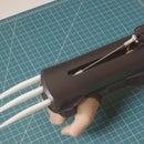
Step 36: [Bonus] How to Embed the System in Armor Gauntlets
![[Bonus] How to Embed the System in Armor Gauntlets](https://content.instructables.com/FUI/I165/HEXSS5J8/FUII165HEXSS5J8.jpg?auto=webp&fit=bounds&frame=1&height=1024&width=1024auto=webp&frame=1&height=300)
![[Bonus] How to Embed the System in Armor Gauntlets](https://content.instructables.com/F1Y/AO6D/HEXSS5J9/F1YAO6DHEXSS5J9.jpg?auto=webp&fit=bounds&frame=1&height=1024&width=1024auto=webp&frame=1&height=300)
If you want to learn how to make your own armor, be sure to check out:

First Prize in the
Game.Life 3 Contest

Participated in the
Lamps & Lighting Contest


