

Introduction: Black Box Timelapse


Black Box Timelapse is a simultaneous timelapse recorder and player, which I built using a Raspberry Pi. It is battery-operated and so I can bring it to different places and set it up.
Why not use an iPhone? Simple: the iPhone looks like a device and so people respond to it like a devie, rather than an art object, which invites curiosity.
Overview on How it works
The video is displayed on this small screen and essentially stacks images over time. You can also plug in an HDMI cable to a monitor or projector if you want to see it in a larger format.
It automatically runs when you plug it in or activate the battery. Right now, the camera takes a new images every 10 seconds and cycles after about 800 images, such that the timelapse will always show the last 2 hours of what happened in a space.
In version 2, this will be controlled with potentiometers, so that you control how often the camera will take images and how quickly it will cycle.
This Instructable will show you both the software configuration and software code as well as the physical fabrication steps I did to make this project come to life.
Step 1: Basic Raspberry Pi Set Up
We're going to make sure we have a few things in order.
First, make sure your Raspberry Pi is properly configured with the basic setup using my Ultimate Raspberry Pi Configuration Guide Instructable.
After this, we will want to make sure that we follow this Instructable on how to mount a USB Thumb Drive on the Raspberry Pi.
These two guides will make it so that we can save timelapse images onto a USB drive and that the Raspberry Pi will be easily configured. We will also add the ability to use the camera on the Raspberry Pi and later on, automatically launch a Python script upon startup.
Step 2: Gather Components


These are the components I'm using, which took awhile to research and figure out.
- Raspberry Pi
- Small TFT monitor, which I ordered from Adafruit for $45.
- Rechargeable 12V battery, with USB output*
- USB battery that outputs 2A. Currently, I'm using this one from Adafruit, which has been reliable, thought a bit heavy
- small USB 3.0 dongle
- RCA male-to-male coupler
- Micro USB for running out to the battery
- Perf board with: 3-position switch, leads for recharging and GPIO.
- GPIO (not used for version 1)
* This 12V battery ended up having problems with the USB output. I was hoping to have one battery run the show, but the Raspberry Pi ended up spiking the power needs when the camera was taking a picture and then the battery would cause a voltage drop, forcing the Raspberry Pi to reboot
Step 3: Battery Charging Mechanism


The electronics portion of this Instructable isn't as well-developed as I'd like. I'm going to improve upon this in the future.
What I ended up doing was making a perf board that includes a GPIO with an ADC chip to control the potentiometers. However, I ran out of time to write the software for potentiometers, so will have to come back to this. So, for the perf board, we are just using a charging circuit for the 12V battery.
This brand of battery has a the same input and output jack, so I rigged up a simple mechanism which has a three-position switch. In the up position, the 12V battery supplies power to the monitor via the video cables.
In the down position, it will look for the charger, as the female connector.
In the neutral or middle position, no power will be active.
I tie all the grounds together (video, battery, charger) and the switch will connect the positive wire of the battery to either to the video monitor, the charger or nothing.
The USB battery isn't part of this circuit and has an on/off switch.
Step 4: Install Picamera and Activate


We will be using the Picamera libraries, which provide a very easy-to-use Python interface into the camera module. Full details of the package are here.
First, we do some housekeeping. From the command prompt, do your standard updates and upgrades, type in:
sudo apt-get update
then:
sudo apt-get upgrade
you will see lines of Linux install code and will have to wait awhile.
Now, install the package itself with:
sudo apt-get install python-picamera
Finally, we want to enable the camera itself. Type in:
sudo raspi-config
This will bring a configuration menu, where you can Enable the camera, which is disabled by default. Enable the camera and reboot.
Step 5: Test Picamera

At this point, you'll want to have the Pi hooked into a monitor, rather than ssh.
Make sure your Raspberry Pi camera is properly connected to your Raspberry Pi. I keep referring to this video guide for proper orientation of the ribbon cable.
Create a simple Raspberry Pi preview script
nano cam_preview.py
now, type in this script:
-----
import time
import picamera
with picamera.PiCamera() as camera:
camera.start_preview()
time.sleep(2)
while True:
time.sleep(10)
----
ctrl-X, return will save
run it:
sudo python cam_preview.py
What you should see is the camera showing a preview image.
Step 6: Diagram Code

This is the full flowchart of the code interaction. I wrote this out to help figure out how the interaction model will work.
Even though I didn't use the pots for this version, the flowchart technique is super-helpful, especially when it comes down to working with the Raspberry Pi, which can be tedious to program.
Step 7: Write the Python Code
This didn't take a super long time to do, but did take some wrangling.
Looking at my original flowchart, I followed most of the steps.
Step 8: Setup Python Code to Auto-launch on Startup
Using my Instructable: Launch Python script on startup, I built a launcher.sh script and edited the crontab to automatically start the Python code.
The escape key will exit the script.
Step 9: Make an Internal Camera Mount


I based my camera mount on an existing STL model of a Raspberry Pi camera enclosure on Thingiverse.
Mine will be mounted inside the black box and needs to have "wings" so that it can be attached to the interior of the box.
Using 123D Design, I added these components and then 3D printed the mount, attaching the camera inside and sealing the two pieces of the mount with epoxy.
Step 10: Design Fabricated Parts


I set up a basic design using Illustrator of what I want the Black Box Timelapse to look like. It consists of a monitor, a camera and inside, a Raspberry Pi and various batteries for mobile use.
The main idea is to:
(1) use as much digital fabrication techniques as possible, i.e. no saws and absolutely minimal sanding and touch-up work.
(2) make a hand-painted aesthetic, using wood with household latex paint.
(3) try for making this as small as possible. final dimensions of the armature are 8" x 7.5" x 5", which the panels adding another 1/4" in every direction.
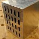
The Panels
These will be made of 1/8" wood, which will be attached to an interior armature. The look that I'm going for is a hand-painted look which will show the 1/8" edges. These will be painted in white, while the faces of the panels will be painted black, kind of like a magician's box.
The back panel has holes for venting, and all of the electronic components: the switch, the female plug for the 12V charger and the potentiometers (to be added in the future), and an LED, also to be added down the road.
The Armature
This is cut from 3/8" wood, which is the maximum thickness that the laser can cut. I went through a few iterations to figure out how to get the camera mount to fit next to the monitor.
Interior Pieces
These are also cut from 1/8" wood, though not painted. We'll have an interior shelf for the perf borad and USB battery to sit in.
Process
It took me a little while to get the exact fittings for these. I did a fair amount of cardboard prototyping to nail these down.
Step 11: Build Internal Armature


After cutting the 3/8" plywood on the laser-cutter, I aligned the armature pieces with blue tape.
Without any jig, which wasn't really necessary, I began nailing this together with a brad nailer, using 5/8" nails. It assembled reasonably square in just 5 minutes.
Step 12: Cardboard Prototype the Panels


Once the armature was ready, I began preparing the panels. Essential to fitting everything together was a series of cardboard prototypes, which is both cheaper and faster than consuming all the wood.
Step 13: Paint 1/8" Panel Black

I had several 30" x 20" panels of 1/8" birch ply for the cutting. With the cardboard prototypes finished, I was ready to cut them.
It's a lot easier to paint one big panel than hand-painting 6 smaller ones, so I painted it before cutting this piece with 1 coat of primer and 2 coats of low-VOC latex paint.
Step 14: Lasercut Painted Panels


Careful on this step to get everything just right.
Now, I I laser-cut the painted panels.
Additionally, the top one will hold magnets and I laser-etched the underside to fit 1/4"x1/16" magnets, which will we insert later.
Step 15: Clean Edges on the Belt Sander


This infringes on the idea of digital fabrication by using traditional shop tools, but we need clean surfaces for paint and primer.
Step 16: Touch-up Paint on Panels

The laser cutter creates some burnt edges, so you need to touch-up the paint on the panel faces. This doesn't take long and a small foam brush will do the trick.
Step 17: Paint White Edges + Touchup


This step is a lot more tedious than it looks. I ended up getting into the zen of paint and learned oodles about foam brush painting techniques.
Step 18: Glue Screen Holder


I glued the screen mount onto the underside and adjusted the position with my fingers before the glue dried to get the alignment just right.
In figure iterations, such as version 2, I will 3D print a better screen holder. The Adafruit TFT 913 monitor has flimsy cabling and tends to break or sever easily. This technique doesn't protect it, but works for now.
Step 19: Glue Shelf Holder


I etched the underside with locations for where the shelf holder will go, which made it easy for figuring out where to apply the glue.
Step 20: Brad Nail Panels Onto Armature


I was patient on this step and took my time with alignment. While the armature can be a bit wonky, the panels need to be just right.
Going for the hand-painted/hand-crafted look means that it doesn't have to be exact, but just kind of close.
But I was pleased: it came out really well!
Step 21: Final Paint Touchup

Spackle, then sand, then paint over the holes where the brad nails went. This is standard touch-up procedure and went quickly.
Step 22: Add Magnets!


With a guide that I cut out from 1/8" wood, I used a transfer punch to figure out where to drill the magnet holes in the armature.
For the top panel, I used a hammer (no steel) to pound the magnets into the underside of the panel. They fit in very cleanly. No adhesive needed.
Step 23: Near Completed Enclosure


This isn't really a step, but more of a look-at-how it went.
This took way longer than I planned to make. Software is easy, fabrication is hard.
Step 24: Epoxy Magnets to Armature


I used epoxy with toothpicks and rubber gloves to adhere the magnets into the armature frame.
Step 25: Final Assembly


Admittedly this step, which I realize is one of the more important ones is ill-documented in terms of photographs.
Sorry, I'll fix this soon (deadlines, deadlines).
The important parts:
- Drill a hole for the camera mount that matches the hole on the panels.
- I used button-head screws (M2) to attach the camera mount to the box. No external bolts were needed. The screws did a self-tapping maneuver, saving me some steps.
- The monitor is press-fit into the opening
- USB battery and perf board go on the the top shelf
- Everything else goes underneath
- Velcro the bottoms of the Raspberry Pi, perf board, 12V battery and USB battery to the shelf and their respective places
- Make all cable attachments: starting with monitor and working your way backwards
- Put the 12V charger plug into the hole in the back panel (press-fit)
- Put the 3-way charging switch into the hole in the black panel
Step 26: Final Project

Ba-da-da-da-da. Done!
Version 1 of the Black Box Timelapse is finished.
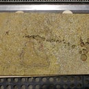
Below are some of the preliminary videos that I shot with it. The way the USB drive is formatted, you can remove the drive from the Raspberry Pi and assemble the video as sequenced image files.
Things that will change in version 2
* Adding an support for changing the frame rate with potentiometers; the circuit is finished but the code is not
* Rebuild the amature so that we can use press-fit magnets instead of epoxy, which is messy
* Some better documentation, especially for the final assembly
I hope this was helpful!
Scott Kildall
For more electronics projects, you can find me here:@kildall or www.kildall.com/blog
Timelapse of the Laser/3D room at Pier 9
Timelapse of my artist talk at Pier 9 on May 13th, 2014


