

Introduction: Blinky Lights Using Arduino and LumiGeek


I used the Arduino UNO combined with three LumiGeek shields to run lighting. LumiGeek has dedicated shields to support 1 Watt RGB LEDs that require constant current, Addressable RGB LED Strip, and Non-Addressable RGB LED Strip.
Step 1: 1 Watt RGB LEDs (2x)
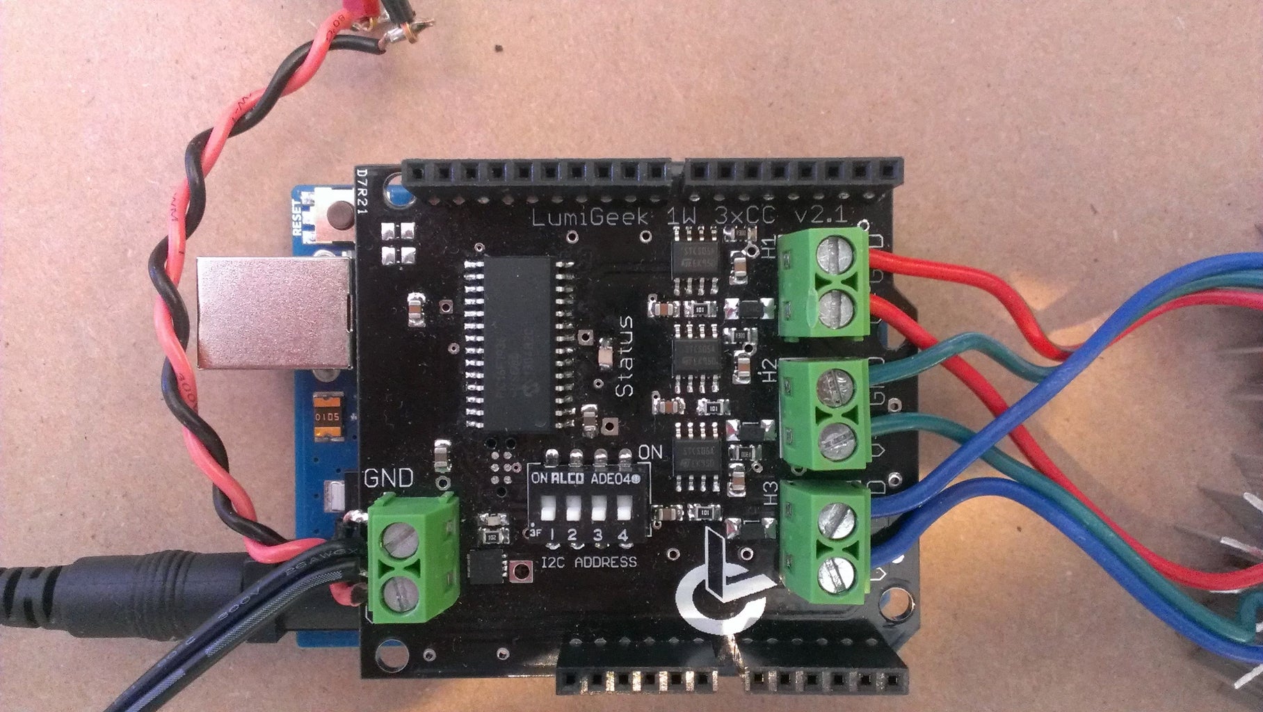


I wired these in series and powered them with the 12 Volt source on the Power Supply. The LumiGeek shield that powers these is the 3XCC - it provides constant current so the LEDs don't fry (the LEDs decrease in resistance as the heat up so the board manages this in order to provide a constant current).
Step 2: 1x Addressable RGB LED Strip


I used LumiGeek's 1xAddressable shield to drive the Addressable RGB LED Strip; this shield can control a single addressable strip.
Step 3: 4x Non-Addressable RGB LED Strip


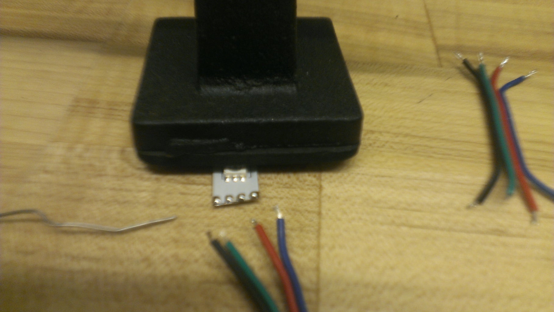


I used LumiGeek's 4xRGB shield to drive the Non-Addressable RGB LED Strip; this shield can control up to four (4) different strips.
Step 4: Programming the Lighting


The shields provide some basic functionality that made is super easy for me to get the 1 Watt RGB LEDs to shine GGB International Orange, and fade between random colors on the non-addressable RGB LED strip. Making the addressable RGB LED strip bend to my will of emulating cars of various headlight hues and speeds was a bit more challenging and my friend John "Parts" Taylor of LumiGeek coached me through the process of shifting pixels and assigning constrained random colors (various shades of white/yellow) and making the fastest "car" morph into a red/blue "police car" ~1 every 7 times (constrained random). I have attached the INO file that is running the Arduino UNO and three (3) LumiGeek shields.
Attachments

Step 5: Power Supply; Selecting and Mounting


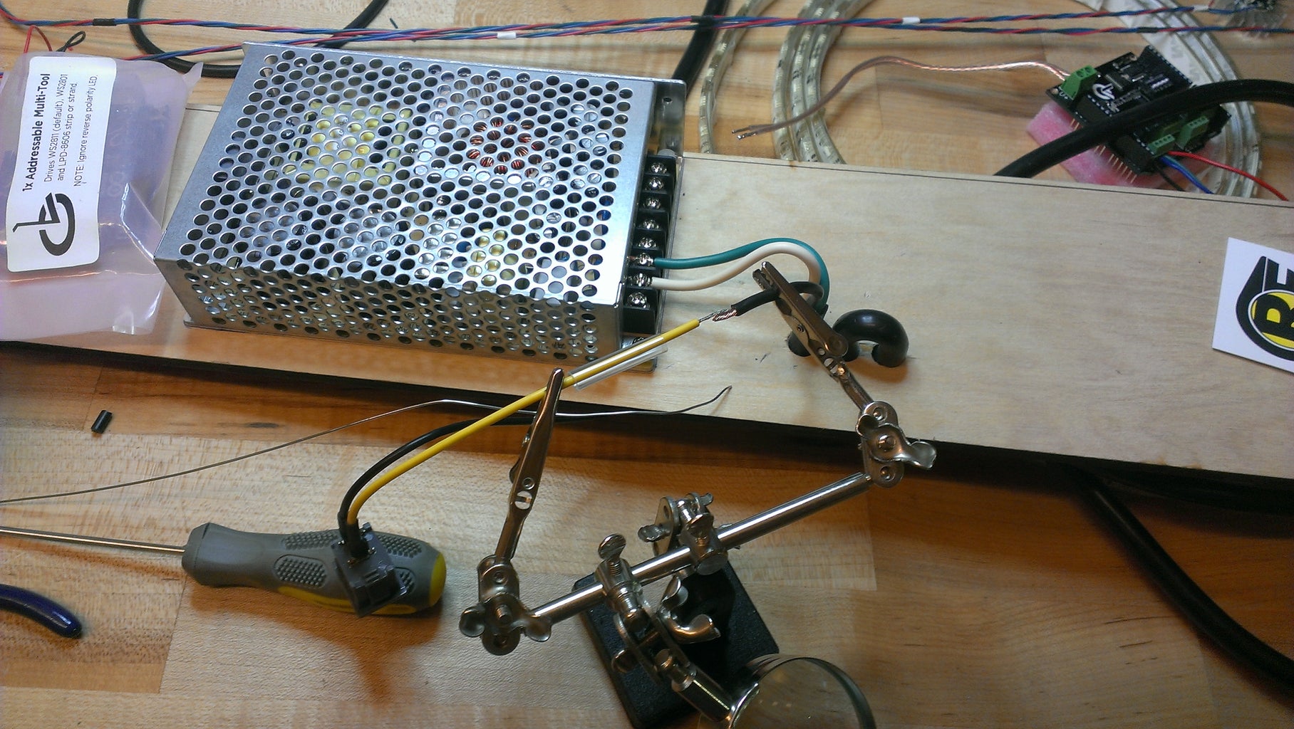
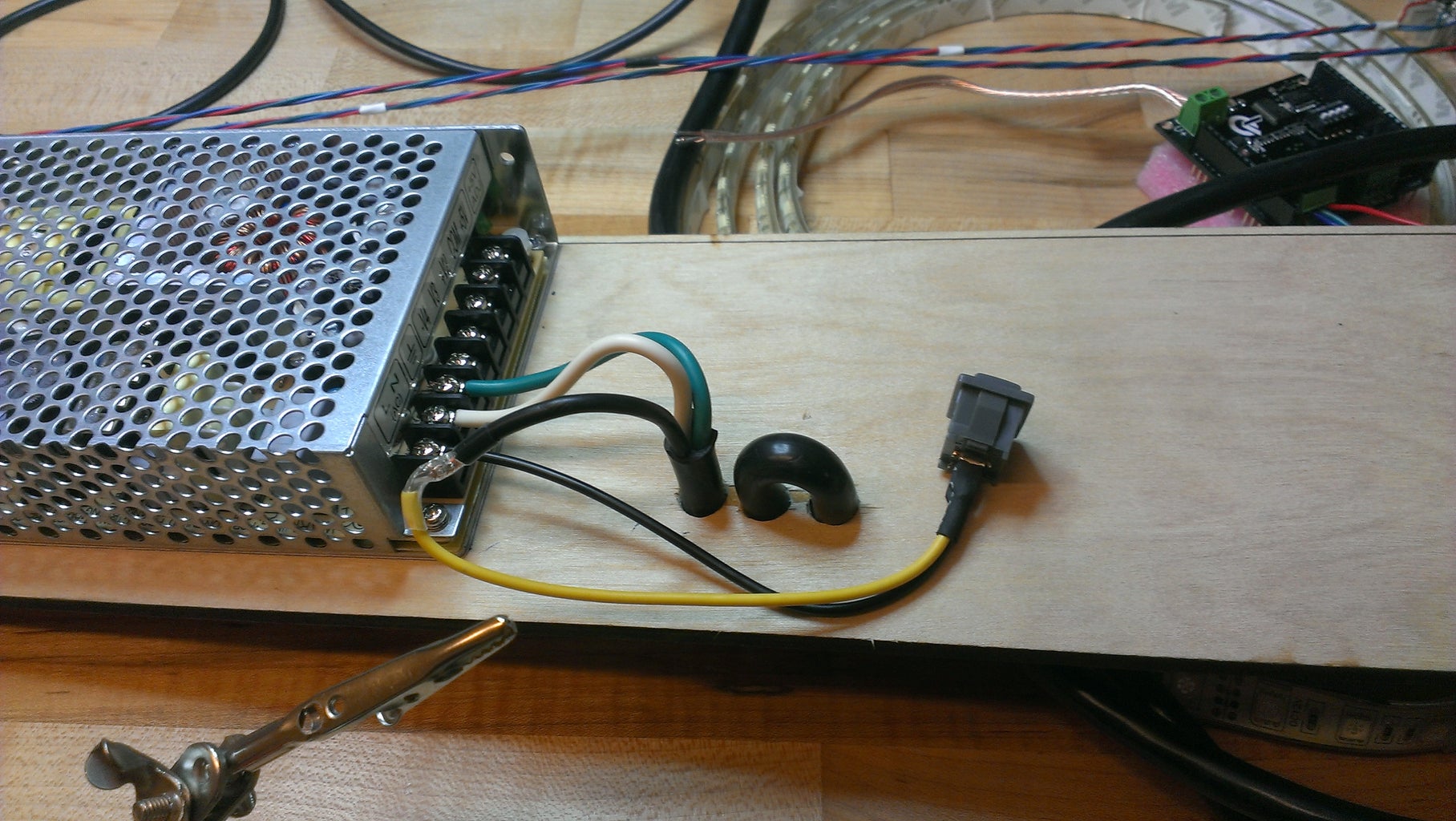


I selected a power supply that provides 12 Volt and 5 Volt for a total wattage of ~80 Watts. The RGB LED Strip I used requires ~20 Watts per meter and the 1 Watt RGB LEDs and very low wattage requirement. I lasercut a platform to fit on the back side of the Living Wall on top of the Base. I then used the Drill Press to make three large holes to thread the power cord through to ensure that it would be yanked out if tripped over and the Living Wall would potentially violently fly across the room (possible design error...).
Step 6: Putting It All Together


I assembled the properly coded boards onto the mounting board and powered everything up. I added quick release clips to the lighting on the GGB after realizing that it will not have a permanent home on top of the Living Wall, so I'm prepped to separate the two pieces at a later date.


