

Introduction: Bluetooth Controlled Message Droid --R2Blue2(/What Not to Do)


This is an instructable for a bluetooth controlled Message Droid. I call it R2Blue2. It moves around and displays messages that you type using your phone or computer. Atleast it was supposed to. Due to many problems such as underpowered batteries and bad cable management I wasn't able to extract the performance necessary. I will explain the problems that plagued this build later.
The messages are sent over a bluetooth connection between the sender and the bot. For my usage, I used a HTC WIldfire running the Blueterm application to send serial commands to bot. The bluetooth module I used on the bot is Bluesmirf Gold which has a default baud rate as 115200. I don't have an FTDI cable to change the baud rate. The baud rate setting shouldn't matter much but whatever is the baud rate of the module, you should set up a serial port of the same baud rate in the arduino code. Otherwise you'll get undefined states and the bot won't function as wanted < imagine R2D2 scream >.
Step 1: Parts


Arduino Deumilanove
Bluesmirf Gold (or any suitable bluetooth module)
Double line LCD based on the Hitachi HD44780 (most common)
Two 100 rpm geared motors
L298 motor driver
10K potentiometer
Birch strip
Connectors for the birch strip
Ribbon Cable
Lots of single strand wire
General Purpose Board (GPB) ....... if you choose to solder everything
Breadboard
Zip ties
Solder (lots of it if you choose to solder everything)
If you can procure a Arduino shield kit, things will be much easier and more reliable as the present connections to the arduino are not very tight. In India, a shield board is quite expensive and I couldn't find it any where I searched. (if you are from Bangalore and are an electronics geek, you should be familiar with SP Road :P). total cost is about 80 to 100 dollars. The bluesmirf is the most expensive part at 60 dollars.
Step 2: LCD Wiring


The LCD was wired up as shown in the tutorial on LadyAda. I just soldered everything on to a pcb and made an
extension for it using the ribbon cable to allow it to be flexible. I also used a birch strip to make it easily
detachable.
link for the tutorial: www.ladyada.net/learn/lcd/charlcd.html
The connections are tabulated below for easy reference:
Pins Connections
1 Ground
2 +5V
3 Contrast Adjustment Pot
4 Arduino pin 2
5 Ground (always in write mode)
6 Arduino pin 3
7 No connection
8 No connection
9 No connection
10 No connection
11 Arduino pin 4
12 Arduino pin 5
13 Arduino pin 6
14 Arduino pin 7
15 +5V
16 Ground
Step 3: Motor Driver Wiring


The L298 doesn't come in a standard DIP (dual inline package). Hence you can't mount it on a breadboard. You
have to solder it onto a GPB. This is what I did and drew some wires out of every pin to allow for connection to
the arduino and the bread board.
The pin connections are tabulated below for easy reference:
Pins Connection
1 Ground
2 Pin 1 of motor 1
3 Pin 2 of motor 1
4 9V supply of motor
5 Arduino pin 8
6 +5V from arduino
7 Arduino pin 9
8 Ground
9 +5V from arduino
10 Arduino pin 10
11 +5V from arduino
12 Arduino pin 11
13 Pin 1 of motor 2
14 Pin 2 of motor 2
15 Ground
This is the easiest connection scheme and it uses the least no of arduino pins, 4. I have made the enables always
high by connecting them to +5V and the current sensing always low by connecting to ground. Look at the pin
diagram to find the pin functions.
Step 4: Bluesmirf Prep

The bluesmirf was connected using birch strip pins on both ends to make it easily removable for transport and safe keeping. While connecting the bluesmirf, the RX pin should go to the TX pin (pin 1) of the arduino and the TX pin should go to the RX pin (pin 0) of the arduino. This is very important so make sure your connections are correct. The GND and Vcc go to their respective pins.
Step 5: Arduino Connections:


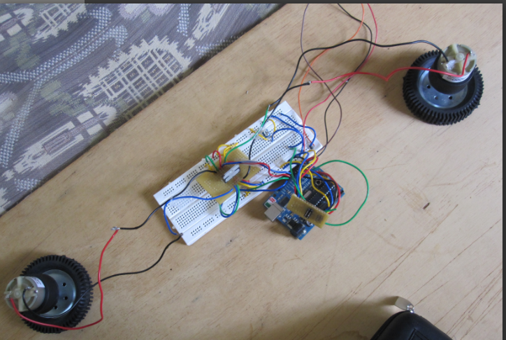
For this project, I've used pins 0 and 1 for communication (as always), pins 2 to 7 for connecting to the LCD, and pins 8 to 11 for connecting to the motor. I used a 9V battery to power it when not connected to the computer, but for testing purposes I used a wall wart with a USB out. I connected all the components to the bread board and used it as an intermediary for connecting it to the arduino. I used a separate 9V battery for the motor power supply.
Step 6: Arduino Code
char in=0;
#include <LiquidCrystal.h>
int i=0;
int z=0;
//setting up LCD using the LiquidCrystal library
LiquidCrystal lcd(2,3,4,5,6,7);
//motor pins
int m1=8;
int m2=9;
int m3=10;
int m4=11;
void setup()
{
//setting up motor pins as output
pinMode(m1,OUTPUT);
pinMode(m2,OUTPUT);
pinMode(m3,OUTPUT);
pinMode(m4,OUTPUT);
//defining an lcd of 16*2
lcd.begin(16, 2);
//starting serial link
Serial.begin(115200);
}
/*the wires might have gotten interchanged a little so fiddle around with which pin goes high when to get the
proper code for movement in any direction*/
//function for forward movement
void forward()
{
digitalWrite(m1,HIGH);
digitalWrite(m4,HIGH);
digitalWrite(m2,LOW);
digitalWrite(m3,LOW);
}
//function for backward movement
void backward()
{
digitalWrite(m1,LOW);
digitalWrite(m4,LOW);
digitalWrite(m2,HIGH);
digitalWrite(m3,HIGH);
}
//function for turning left on its axis
void left()
{
digitalWrite(m1,LOW);
digitalWrite(m4,HIGH);
digitalWrite(m2,HIGH);
digitalWrite(m3,LOW);
}
//function for turning right on its axis
void right()
{
digitalWrite(m1,HIGH);
digitalWrite(m4,LOW);
digitalWrite(m2,LOW);
digitalWrite(m3,HIGH);
}
//function for stopping all motion
void stop1()
{
digitalWrite(m1,LOW);
digitalWrite(m4,LOW);
digitalWrite(m2,LOW);
digitalWrite(m3,LOW);
}
void move_code(char x)
{
if(x=='w')
forward();
else if(x=='x')
backward();
else if(x=='a')
left();
else if(x=='d')
right();
else if(x=='s')
stop1();
}
//function for displaying message while in motion and controlling the movement of bot
void display_move()
{
if(z==0)
{
lcd.clear();
lcd.print("Moving....");
z++;
}
if(Serial.available())
{
in=Serial.read();
if(in=='w'||in=='s'||in=='a'||in=='d'||in=='x')
move_code(in);
else if(in=='%')
lcd_display();
else
{
lcd.clear();
lcd.print("You typed shit..");
delay(3000);
z=0;
}
}
}
//function for displaying message typed
void lcd_display()
{
lcd.clear();
stop1();
in=0;
i=0;
lcd.cursor();
while(in!='%')
{
if(i>32)
{
lcd.clear();
i=0;
}
if (Serial.available())
{
char in=Serial.read();
i++;
if(i>16&&i<=32&&in!='%')
{
lcd.setCursor((i-17),1);
lcd.print(in);
}
else if(in=='%')
{
z=0;
in=0;
break;
}
else
lcd.print(in);
}
}
}
//main function
void loop()
{
display_move();
}
Step 7: Housing and Final Construction:


I used an old plastic box meant for sweets to house the arduino and the breadboard. I cut small holes in the lid to allow the ribbon cable for the LCD, the connector for the bluemsirf, and the wires to the motors go out. I used a rectangular piece of wood to hold the motors and attach it to the base of the box. I wanted to mount the LCD high by using some ice cream sticks, rubber bands and a stationary clip but the lid wasn't stable enough. I used some ice cream sticks for balancing the bot cause i didn't have any castor wheels.
Step 8: Why It Screwed Up

The main reasons for it not working well were:
1. The batteries were not powerful enough, all the pics where the lcd is bright were taken using a USB wall wart. And the wheels barely used to turn when in movement mode.
2. The cable management was not clean so qt every stage I had to keep checking whether any wires had come off. And if they had come off, it was very difficult for my fingers to go through the maze of wires to reconnect the loose wires.
3.The Housing I had chosen was very small and fitting all the components with enough space for arrangement was very difficult.
How one should rectify the above problems:
1.Get a bunch of AA rechargeable batteries and use a 6 pack of them. That should be enough for movement at a relatively controllable speed. These motors were rated for 9V so using lower rated motors could help increase the speed.
2.Get an arduino shield kit and connect all loose wires to the shield. Since the shield fits snugly on an arduino, no wires will come loose during any stage.
3.Get a bigger box or leave all the components out in the open instead of stuffing them into the box. That messes up the chances of the components working properly cause the stresses on the wires can loosen the wires from their original location.
Step 9: Controls and Conclusion


So if you've done everything correctly, you should be able to use the following commands to control your bot.
The controls for the bot are as follows:
Character Function
w Forward
a Turn left
s Stop
d Turn right
x Backwards
% stop and go to display mode
% When in display mode, clear the screen and return to movement mode
It can be controlled as i said before by using any computer or phone running a terminal program which can communicate over bluetooth.
I've been wanting to make this ever since I got my hands on the bluesmirf module 7 months ago and its been a nice experience involving many topics such as motor control, lcd displays and serial communication, even if it didn't turn out as well as I planned. Atleast I have a clean LCD connection system for future endeavours and i established that the Bluesmirf works perfectly. All in all it
took me 3 days to do this. If you have better equipment and a shield kit, it should take even lesser. Basically, it was a lot of fun. I would like to thank my parents for running around with me when I ran out of parts and I had to go buy them when it was raining cats and dogs. Without them I would have been stuck with a fried LCD and wouldn't have been able to finish this. I don't have many pictures as I started the instructable after I had almost finished the bot. Any queries? Please comment.
And I'm entering this in the Microcontrollers and Making Stuff Move contests. I promise that if I win in either of them, I will churn out much better projects and improve this one to make it work perfectly (that robot kit they are giving for the Microcontroller contest is perfect for this :D and a Bus Pirate will be an excellent addition to my non existent set of equipment).So please vote for me if you like my Instructable!!!!

Participated in the
Microcontroller Contest

Participated in the
Toy Challenge

Participated in the
Make It Move Challenge


