

Introduction: Bluetooth Thermometer


This instructable details the making of a simple 2 channel thermometer using 100K thermistor probes, a Bluetooth module and smartphone. The Bluetooth module is a LightBlue Bean which was designed to simplify Bluetooth Low Energy app development by using the familiar Arduino environment for programming the module.
After stumbling around for a while trying to figure out how to get the temperature data from the Bluetooth module to my iPhone, I found an app called EvoThings which simplified the app development side of the project considerably. I don't have a Mac (shocking I know!) which limits my ability to develop an iPhone app, and I don't have time to decipher the new Microsoft tools which evidently support cross platform development for iOS and Android. I have done several HTML5 style apps but the only way to get at Bluetooth data is through plugins for Cordova which looked like more of a challenge than I had time for. EvoThings provides a very easy to use set of tools that turned the Bluetooth-to-iPhone challenge into a cakewalk. And I like cake!
Overall I found the combination of Lightblue Bean and EvoThings to be a very practical solution with low time investment.
Step 1: Things You'll Need


I used a commercially available thermistor probe for one channel because I wanted the thermistor sealed for immersion into liquids. For the second channel, I made a basic probe from a thermistor, some 26 gauge wire and a 3.5mm headphone plug. You are free to use any thermistors you want and you can make your own probes from thermally conductive epoxy and plastic straws/coffee stirrers for example. What follows is what I used - it is not intended to be a prescriptive list!
Hardware
- 1 x 100K Thermistor probes. Model Extech TP890. These are commonly available on ebay and amazon.
- 2 x 2.5mm Stereo jacks which matches the 2.5mm plug on the Extech probes. I scavenged 3.5mm jacks from an old computer so I cut the plug off the Extech probe and replaced it with 3.5mm plugs. You should avoid this an just use 2.5mm jacks, or use an off-the-shelf 2.5mm to 3.5mm stereo adapter plug.
- 100K thermistor bead plus 26 gauge wire plus 3.5mm stereo plug if you want to make your own probe. If not, buy a second Extech probe!
- 1 x Lightblue Bean by Punch Through Designs. This is the Bluetooth module programmable as an Arduino development board. The module is kinda pricey but it removes a lot of complexity. They are running a Kickstarter campaign for the next generation device which might be worth considering.
- 2 x 1/4W 100K resistors which are used to divide the reference voltage for the thermistors. I used 5% resistors but higher tolerance resistors are generally less temperature sensitive and will provide better performance. 1% is a good tolerance value for this.
- Soldering iron and solder
- Wire cutters and some small lengths of 26 or 28 gauge hookup wire.
Software and Firmware
- For programming the Bean, you will need the Bean Loader app. I've used windows so all links will be Windows specific. Everything you need to get started with the Bean including the Arduino specifics is available from the LightBlueBean site
- The EvoThings workbench for the smartphone app is available here. All the "getting started" documentation is available there as well. It is very well documented.
Step 2: The Circuit and Electrical Construction


A thermistor is a temperature dependent resistor. The Extech probe has a negative temperature coefficient which means that as the temperature increases, the resistance decreases. The resistance value is measured with a simple circuit which creates a voltage divider with the thermistor in one leg, and a fixed 100K resistor in the other. The divided voltage is fed into an Analog Input channel on the Bean and sampled in the firmware.
To build the circuit, I scavenged 3.5mm audio jacks from an old broken PC. A multimeter was used to determine the two points on the PCB that corresponded to the tip and first band of the probe. Wires were soldered to the audio jacks and to the Bean as shown in the images. The audio jacks were stuck to the prototype area of the Bean using double sided tape. The tape I used is automotive grade decal tape which creates a very strong bond between the tow parts.
Step 3: Probe Coefficients

As common as the Extech probe is, the Steinhart-Hart coefficients aren't published anywhere that I could find. Fortunately there is an online calculator that will determine the coefficients from 3 temperature measurements you provide.
http://www.thinksrs.com/downloads/programs/Therm%2...
What foillows is the basic procedure I used to arrive at the coefficients. Won't earn any points for style but good enough to get you to say +/- 1 degree accurate (a total thumbsuck on my part) .... depending on the accuracy of your reference thermometer and multimeter of course! My multimeter is a cheap no-name brand unit I bought many years ago when money was tight. Money is still tight and it still works!
To calibrate, we need three resistance readings from 3 temperatures.
- Near freezing by adding ice to a glass of water and stirring until the temperature stabilized. Once stabilized, use the multi-meter to record the resistance of the probe and the reference thermometer to record the tmeperature..
- Now place the probe into a glass of water at room temperature, allow the probe to equalize with the water temperature and record the temperature on your reference thermometer and the resistance reading on your multi-meter.
- Place the probe into a glass of hot water and record the resistance.
Temperature Resistance 5.6 218K 21.0 97.1K 38.6 43.2
This whole process is a bit of a chicken and egg situation since you need a calibrated thermometer to record the temperature and a calibrated multi-meter to record the resistance. Errors here will result in inaccuracy in the temperature measurements you make but for my purposes, +/- 1 degree is more than I need.
Plugging these recorded values into the web calculator yields the following:

The coefficents (A,B and C) are plugged into the Stenhart-Hart equation to deterrmine the temperature from a sampled resistance value. The equation is defined as (source: wikipedia.com)

Where T= Temperature in Kelvin
A, B and C are the Steinhart-Hart equation coefficients we are trying to determine
R is the resistance at temperature T
The firmware will perform this calculation.
Step 4: Firmware


The thermistor voltages are sampled, converted to temperature and sent via Bluetooth to the EvoThings app running on the smartphone.
To convert the voltage to a resistance value within the Bean, a simple linear equation is used. The derivation of the equation is provided as an image. Instead of converting the sampled value to voltage, since both the ADC and the input voltage are referenced to the same battery voltage, we can use the ADC value instead of the voltage. For the 10bit Bean ADC, full battery voltage will result in an ADC value of 1023 so we use this value as Vbat. The actual value of the divider resistor is an important consideration. Measure the actual value of the 100K divider resistor and use the measured value in the equation to avoid an unnecessary source of error due to resistor tolerance.
Once the resistance value is calculated, the resistance value converted to temperature using the Steinhart-Hart equation. This equation is described in detail on Wikipedia.
Because we have 2 probes, it made sense to encapsulate the probe functionality into a C++ class.
The class encapsulates the Steinhart-Hart equation coefficients, the nominal divider resistance value and the analog port to which the thermistor is connected. A single method, temperature(), converts the ADC value to a resistance value and then uses the Steinhart-Hart equation to determine the temperature in Kelvin. The return value subtracts absolute zero (273.15K) from the calculated temperature to provide the value in Celsius.
The power of the Lightblue Bean is evident in the fact that all the Bluetooth functionality is essentially implemented in 1 line of code which writes the sampled temperature values to a scratch data area on the Bluetooth memory.
Bean.setScratchData(TEMPERATURE_SCRATCH_IDX, (uint8_t*)&temperature[0], 12);
Each sampled temperature value is represented by a float which takes up 4 bytes. The scratch data area can hold 20 bytes. We are only using 12 of them. There are 5 scratch data areas so you could transfer up to 100 bytes of data using scratch data.
The basic flow of events is:
- Check to see if we have a Bluetooth connection
- If so, sample temperatures and write them to the scratch data area
- Sleep 200ms and repeat the cycle.
If not connected, the firmware puts the ATMEGA328P chip to sleep for a long time. The sleep cycle is important for conserving power. The ATMEGA328P chip goes into low power mode and stays there until interrupted by the LBM313 Bluetooth module. The LBM313 will generate an interrupt to wake the ATMEGA328P at the end of the sleep period requested, or whenever a Bluetooth connection is made to the Bean. The WakeOnConnect functionality is enabled by explicitly calling Bean.enableWakeOnConnect(true) during setup().
It is important to note that the firmware will work with any BLE client application. All the client needs to do is strip the temperature bytes from the scratch data bank and reassemble them into floating point numbers for display or processing. The easiest client app for me was to use EvoThings.
Attachments

Step 5: Smartphone App

The Evo Things sample app is very close to what I needed with only minor effort required to add the additional display elements to complete the 3 channel temperature measurement device.
The installation and basic operation of the EvoThings platform is very well documented on the Evo Things web site so there is no value in repeating that here. All I will cover here are the specific changes I made to their sample code to display 3 channels of temperature information, extracted from the Bluetooth scratch data area.
After you have installed the EvoThings Workbench, you will find the Lightblue Bean example here (on Windows 64 bit computers):
ThisPC\Documents\EvothingsStudio_Win64_1.XX\Examples\Lightblue-bean-basic\app
You can replace the index.html and app.js files with the files attached to this step. The changes made to the jacascript file extract the 3 floating point temperature values form the scratch data area, and up the the inner HTML of new elements created in the HTML file.
function onDataReadSuccess(data) {
var temperatureData = new Float32Array(data);
var bytes = new Uint8Array(data);
var temperature = temperatureData[0];
console.log('Temperature read: ' + temperature + ' C');
document.getElementById('temperatureAmbient').innerHTML = temperatureData[0].toFixed(2) + " C°";
document.getElementById('temperature1').innerHTML = temperatureData[1].toFixed(2) + " C°";
document.getElementById('temperature2').innerHTML = temperatureData[2].toFixed(2) + " C°"; }
Attachments
Step 6: Enclosure


The enclosure is a simple 3D printed box. I used Cubify Design to create the design but any 3D modelling program will suffice. The STL file is attached for you to print your own. If I had to do it over, I would make the walls a little thicker than they are now, and change the clip design that holds the board in place. The clips break very easily becasue the stress is in the smae plane as the 3D printed layers, which is the weakest orientation for 3D printed parts. The walls are very thin so the snap mechanism is a little on the weak side. I used clear tape to keep the box closed because the walls were too flimsy - not elegant but it works!


Step 7: PC Settings and Bluetooth Configuration

The firmware build and upload cycle for the Bean is all done over Bluetooth. There can only be one active Bluetooth connection at a time. The Bean Loader is available from the Windows App Store
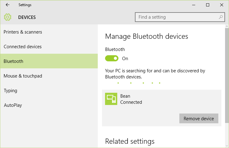
The basic cycle I use to pair and connect ( and repair and reconnect when things go wrong) is as follows: From the Control Panel;/Bluetooth settings, you should see the following screen:

Eventually windows will report "Ready to pair". At this point you can click on the Bean icon and after some seconds, Windows will prompt you to enter a passcode. The default passcode for the bean is 00000

If the passcode is entered correctly, Windows will show that the device is properly connected. You must be in this state in order to be able to program the Bean.

Once you are paired and connected, use the Bean Loader to load the firmware to the bean. I found this to fail more often than not and it appeared to be related to proximity to my computer. Move the Bean around until you find a location that works for you. There are times when nothing will work and the Bean Loader will suggest re-pairing the device. Typically going through the pairing process again will restore connection. You must "Remove the Device" before re-pairing.
The Bean Loader operation is straighforward and well documented on their site. With the Bean Loader open, choose the "Program" menu item to open a dialog to browse to the Hex file provided in the firmware step of this instructable.

Once the firmware is loaded, CLOSE the Bean Loader so that the connection between the Bean Loader and the Bean hardware is dropped. You can only have one connection at a time. Now open the EvoThings workbench and start the EvoThings client on the smartphone or tablet.

When you click the "Run" button, the EvoThings client will automatically load the html page for the thermometer. Click the Connect button to connect to the Bean and you should see temperatures displayed. Success!
Step 8: Conclusion

If everything is built and configured correctly, you should have a working system which will allow you to monitor temperatures with 2 probes, as well as monitor the temperature of the BMA250 sensor on the Bean development board. There is more that can be done with EvoThings - I have just scratched the surface so I leave this experimentation for you! Thanks for reading! If things go wrong, just leave comments and I will help where I can.
Participated in the
Soldering Challenge

Participated in the
Phone Contest


