

Introduction: Boe Bot/Arduino Line Following Robot
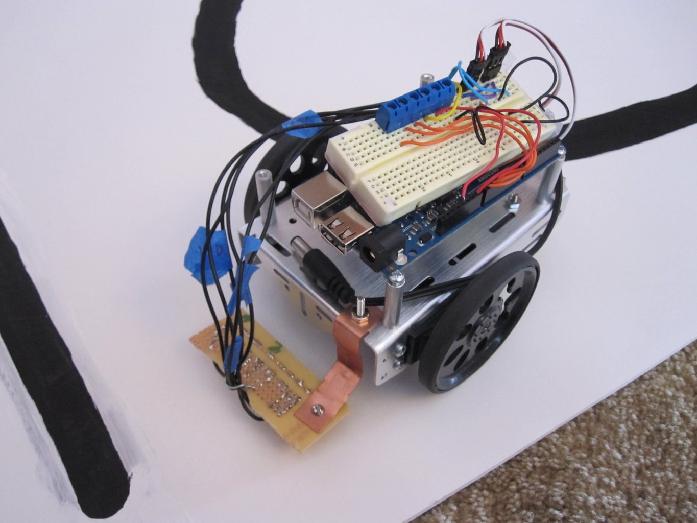


This is a fairly straightforward guide of how to build a line following robot. it uses lights, light dependent resistors (LDRs), an arduino, and a boe bot chassis (any robot chassis with 2 continuous rotation servos will work). it reads the sensors and turns based on the amount of light reflected form the surface below it. the sensors could also be used to detect edges.
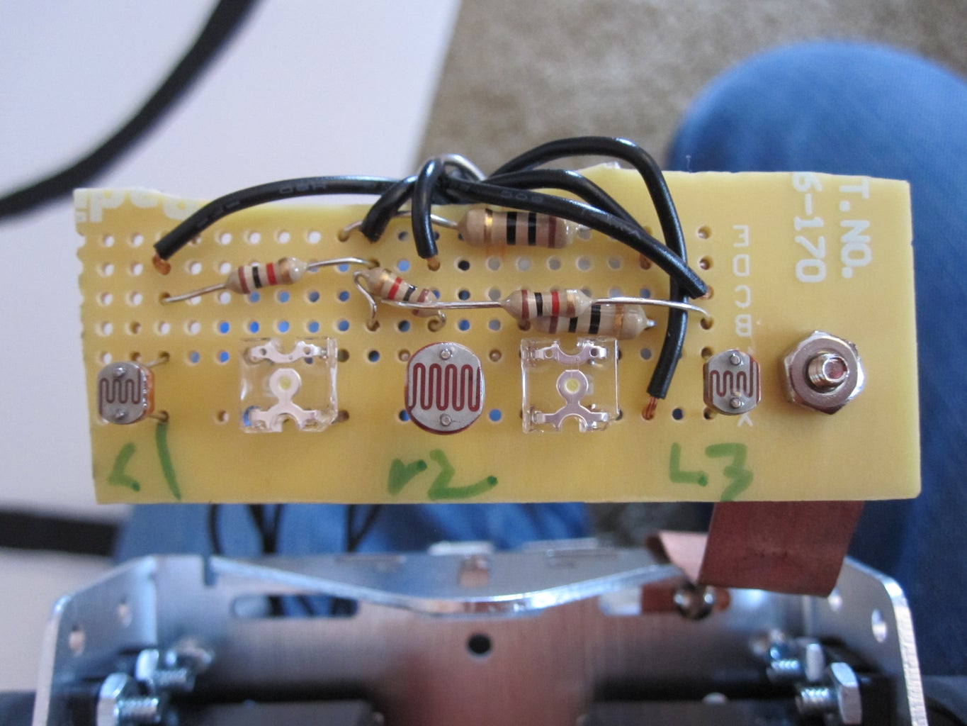
Step 1: Build the Sensor

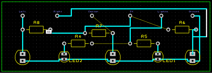
you will have to build the sensor to the included schematic
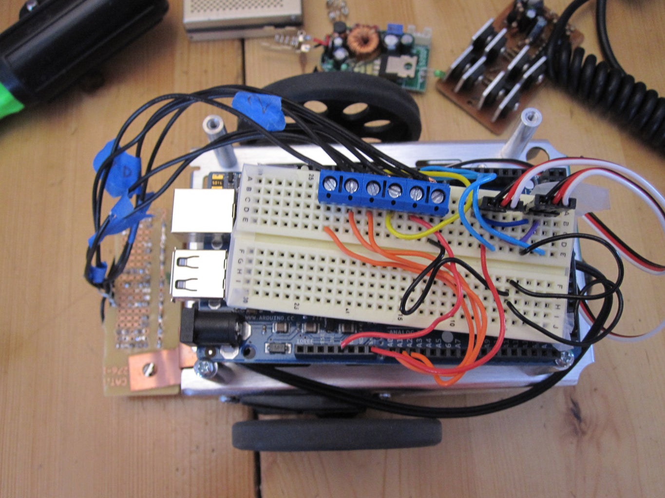
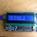
Step 2: Mount the Arduino, and Connect the Wires
i used an arduino mega, but you could use an uno. mounting will vary based on arduino and chassis. you could also use an arduino board of education from parallax.
Step 3: Program It!
// Project 30 - Line Following Robot
#include <Servo.h>
#define lights 7
int LDR1, LDR2, LDR3; // sensor values
// calibration offsets
int leftOffset = 0, rightOffset = 0, centre = 0;
// starting speed and rotation offset
int startSpeed = 125, rotate = 30;
// sensor threshold
int threshhold = 5;
// initial speeds of left and right motors
int left = startSpeed, right = startSpeed;
Servo lefts;
Servo rights;
// Sensor calibration routine
void calibrate() {
for (int x=0; x<10; x++) { // run this 10 times to obtain average
digitalWrite(lights, HIGH); // lights on
delay(100);
LDR1 = analogRead(0); // read the 3 sensors
LDR2 = analogRead(1);
LDR3 = analogRead(2);
leftOffset = leftOffset + LDR1; // add value of left sensor to total
centre = centre + LDR2; // add value of centre sensor to total
rightOffset = rightOffset + LDR3; // add value of right sensor to total
delay(100);
digitalWrite(lights, LOW); // lights off
delay(100);
}
// obtain average for each sensor
leftOffset = leftOffset / 10;
rightOffset = rightOffset / 10;
centre = centre /10;
// calculate offsets for left and right sensors
leftOffset = centre - leftOffset;
rightOffset = centre - rightOffset;
}
void setup()
{
// set the motor pins to outputs
pinMode(lights, OUTPUT); // lights
// calibrate the sensors
calibrate();
delay(3000);
digitalWrite(lights, HIGH); // lights on
delay(100);
// set motor direction to forward
// set speed of both motors
lefts.attach(2);
rights.attach(3);
lefts.write(91);
rights.write(91);
}
void loop() {
// make both motors same speed
left = startSpeed;
right = startSpeed;
// read the sensors and add the offsets
LDR1 = analogRead(0) + leftOffset;
LDR2 = analogRead(1);
LDR3 = analogRead(2) + rightOffset;
// if LDR1 is greater than the centre sensor + threshold turn right
if (LDR1 > (LDR2+threshhold)) {
rotate = LDR2 - LDR3;
left = startSpeed + rotate;
right = startSpeed - rotate;
}
// if LDR3 is greater than the centre sensor + threshold turn left
else if (LDR3 > (LDR2+threshhold)) {
rotate = LDR2 - LDR1;
left = startSpeed - rotate;
right = startSpeed + rotate;
}
else {
left = startSpeed;
right = startSpeed;
}
// send the speed values to the motors
lefts.write(left);
rights.write(180 - right);
delay(5);
}
Attachments

Step 4: Finish It Off
fire it up and send it out on a line (i suggest a line 3/4 to 1 inch wide)
you may have to tweak it, but hopefully not much

Participated in the
ShopBot Challenge

Participated in the
Arduino Challenge


