

Introduction: Bootload an Arduino With a ZIF Socket


Bootloading an Arduino with a ZIF socket allows you to easily program a lot of chips at once without worrying about mangling the pins. The reason for this is that ZIF stands for "zero insertion force," and as the name implies, ZIF sockets don't require any force to take the chip in or out. This means that you do not have to worry about any of the pins bending when you take the chip in and out of the socket. This is particularly useful if you need to bootload a lot of Arduino chips at once for inclusion in an electronics kit or if you need to repeatedly program a chip and transfer it back and forth between a separate circuit board.
Step 1: Go Get Stuff

You will need:
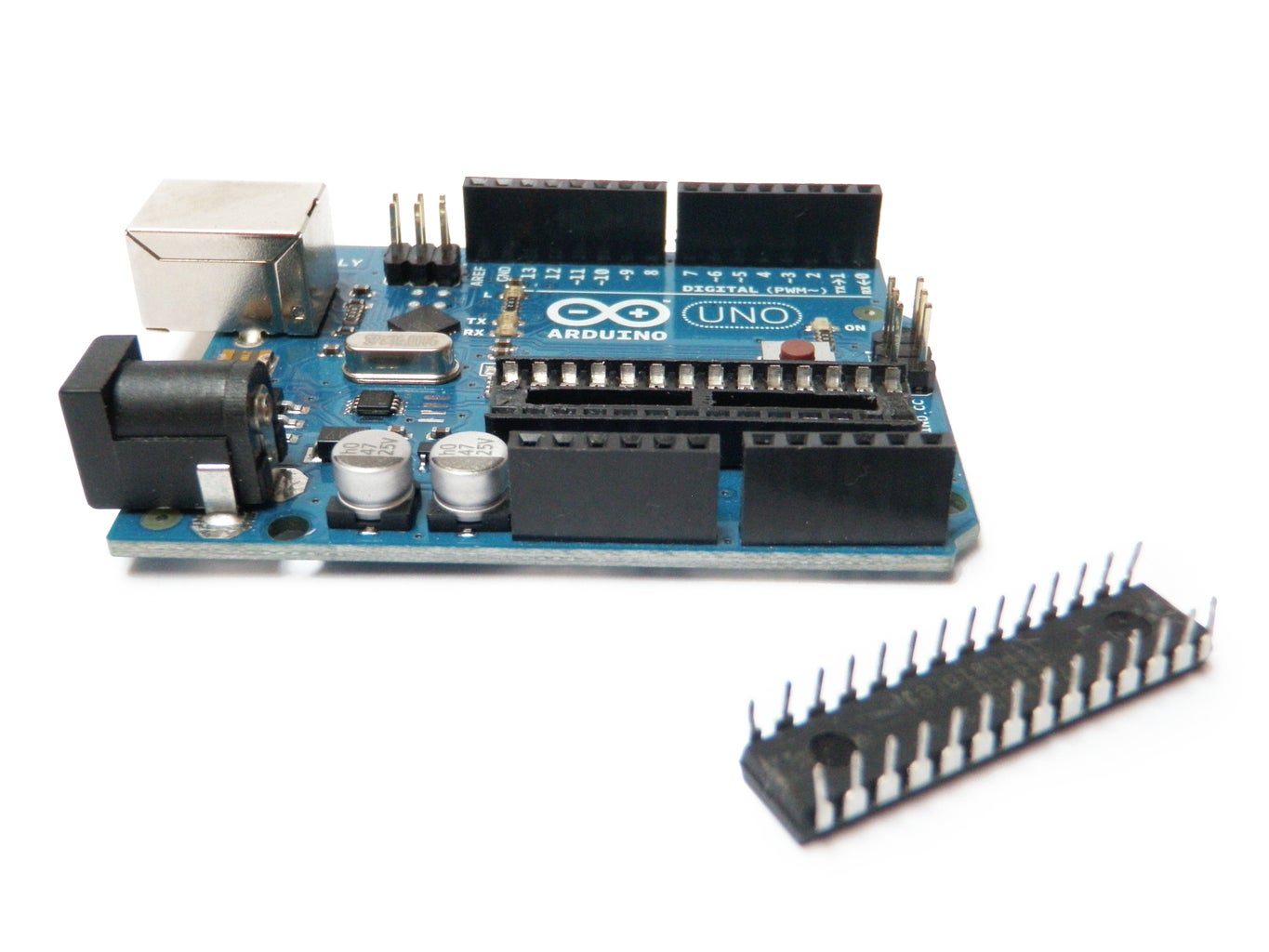
- ATMEGA328 (as many as you want to program)
- USBtinyISP
- An Arduino board
- A ZIF socket
- A breadboard
- 10K resistor
- (x2) 22pF capacitor
- 16mhz crystal
- Solid core wire
Step 2: Microcontroller Pins

Microcontrollers typically ship with the pins bent slightly outwards. This makes them wider than a normal DIP socket like the one used on an Arduino. The chip on the left is an example of this.
A chip that has been properly inserted into an Arduino socket will have pins which are straight (at a right angle to the body of the chip). The chip in the middle is an example of this.
Unfortunately, chips that have been through the process of being forcibly inserted and removed from a normal socket sometimes end up looking like the chip on the right. Notice the pins are bent in every which direction.
Step 3: Remove the Chip


Remove the ATMEGA328 chip from the Arduino board.
The implication in the picture sequence you can simply pull it out with your fingers is a lie (unless your fingers are like vice grips).
The proper way to do it is with a special tool called a chip extractor.
Barring that, I find that anything skinny, flat, and metal works well. For instance, I like to use a mini flathead screwdriver or a dental spatula to do this. I wedge one end under one side, gently wiggle it a little to lift it, and then I repeat this on the other side. After going back and forth a couple of times, the chip should be free and no pins should be bent.
Step 4: Breadboard the Circuit

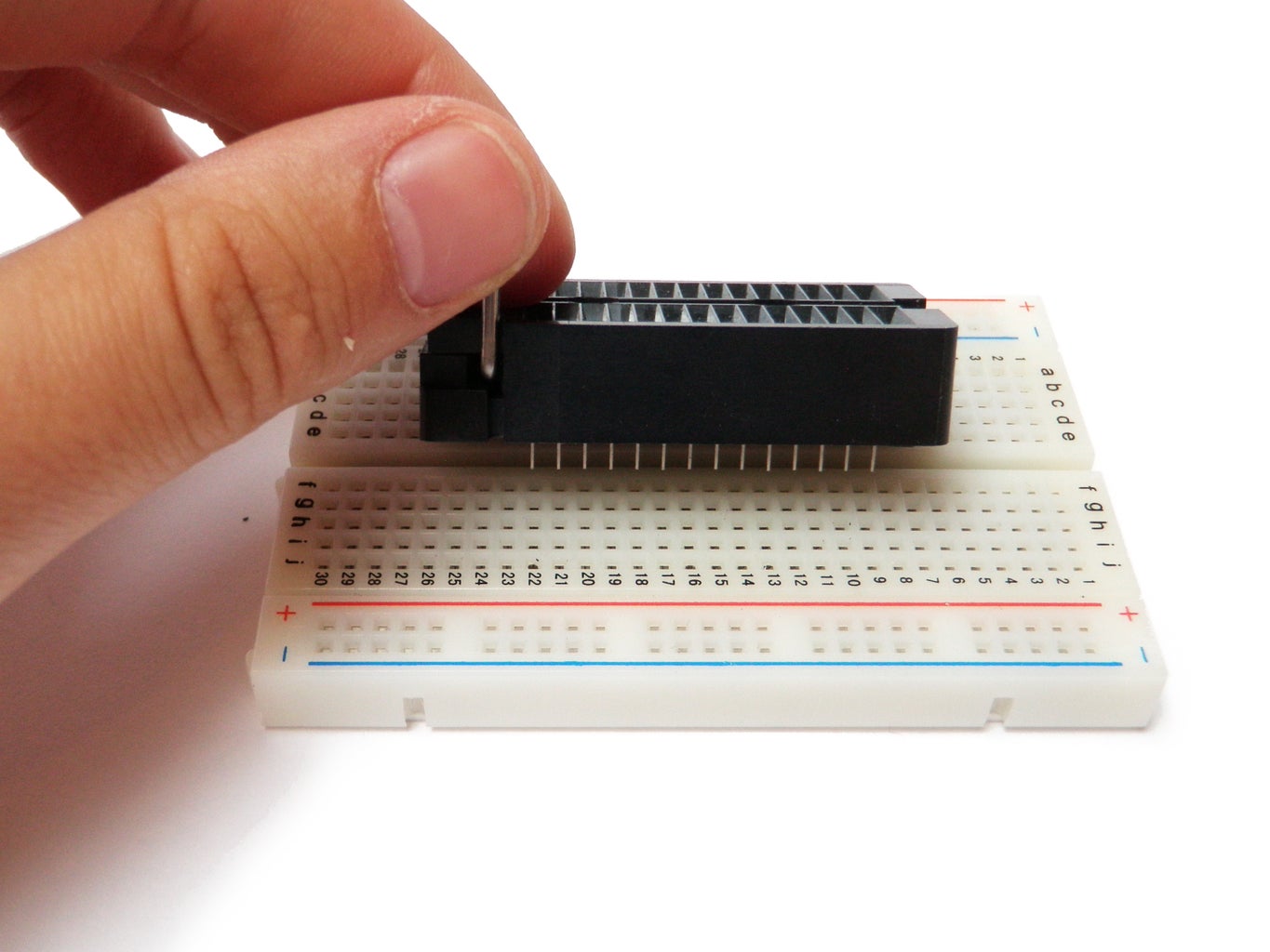


Center the ZIF socket on the breadboard. Consider the side with the lever to be the top of the chip (the notched part of the chip).
Note which row of the breadboard that pin 1 (the top left pin of the chip) is inserted.
Count down to pins 9 and 10. Connect a 22pF capacitor from each of these pins to the ground rails. Also, instal a 16mhz crystal between pins 9 and 10. Be careful that the leads from the capacitors are not touch the body of the crystal.
Connect pin 8 to the ground rail with wire and also connect pin 7 to the power rail.
Now, connect a 10K resistor between pin 1 and the power rail.
Pin 20 and 21 needs to be connect to the power rail and pin 22 should be connected to ground.
Lastly, connect the power rails on each side of the board together and also do the same for the ground rails.
Step 5: Connect the Boards


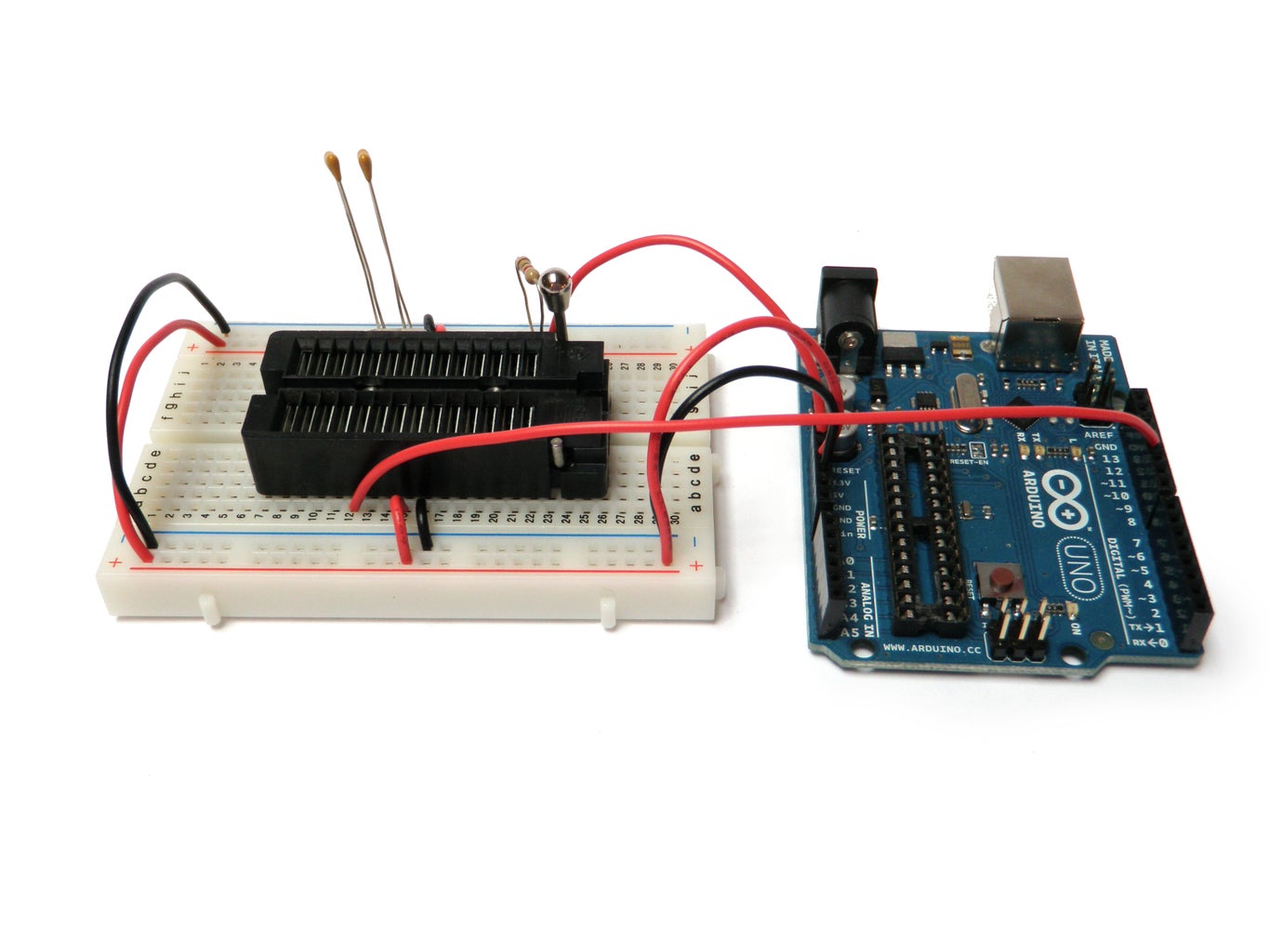
Once the breadboard is complete you need to attach it to the Arduino board
Connect the reset pin from the Arduino to pin 1 of the ZIF socket.
Connect together the 5V pin to the power rail on the breadboard and the ground from the Arduino to the ground on the breadboard.
Finally, connect:
pin 11 to pin 17
pin 12 to pin 18
pin 13 to pin 19
Step 6: Attach the ISP


Attach the small connector from the USBtinyISP to the 6-pin ISP header on the Arduino board such that the red stripe on the connector is closest to the digital pins.
Step 7: Insert the Chip


Insert the chip into the ZIF socket.
Don't forget that pin 1 is to the left of the notch on the chip and this is on the side with the lever.
Once the chip is inserted, pull down the lever to lock it into place.
Step 8: Bootload
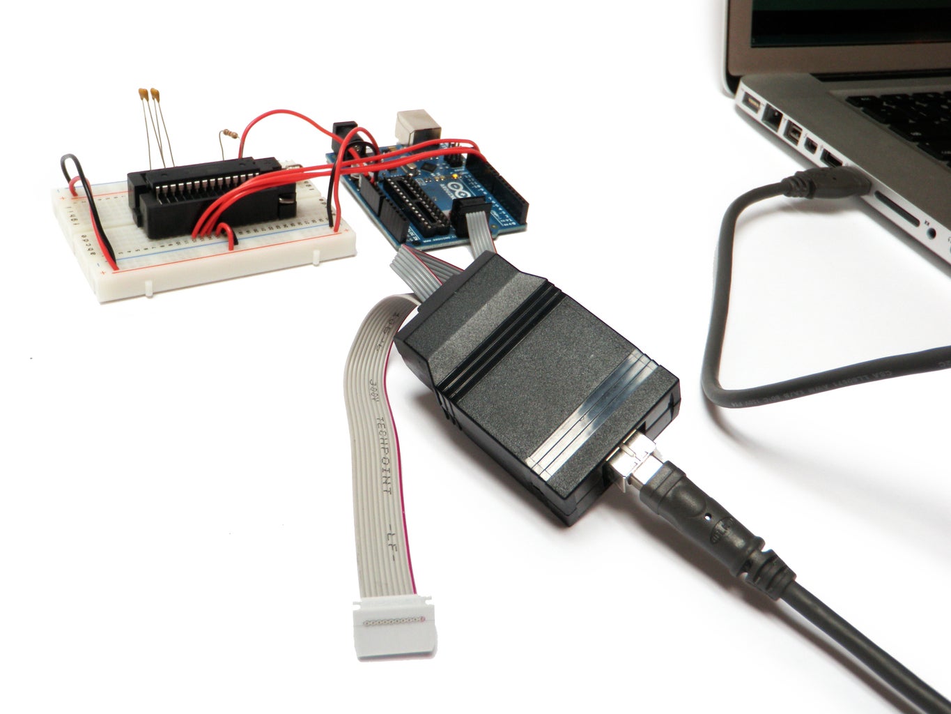

Plug in the USBtinyISP to your computer.
Open the Arduino IDE.
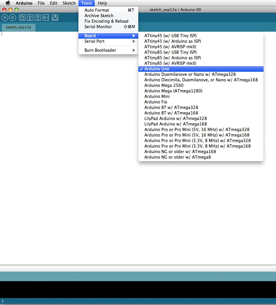
From the top menu select:
Tools > Board > Arduino Uno
Next select:
Tools > Burn Bootloader > w/ USBtinyISP
It will then display at the bottom of the IDE window:
Burning bootloader to I/O Board (this may take a minute)...
A few minutes later it will state:
Done burning bootloader.
Step 9: Rinse. Repeat.


Burn as many bootloaders as you see fit.
If you want to use an Arduino as an ISP, another ISP, or do some other fancy things, check out this page to get started.

Participated in the
4th Epilog Challenge


