

Introduction: Build a ESP8266 Flash Adapter!


Greets!
If you are into WIFI and IoT projects, you have crossed the ESP8266 name before! If you own more than one, you probably hate the connecting wires stage required to flash the bug fix in the prototyping stage. The Flash Adapter mk2 will save your time! You will need few cents of spare materials and about 1h of your time.
Features:
- Saves times
- Saves wires
- Breadboard compatible
- Works on the smallest breadboards
You will find additional pictures on my website: http://www.notenoughtech.com/home-automation/esp8266-flash-adapter/
ESP8266 Flash Adapter prototype v1.0
It’s the easiest to make, but it needs an extra wire. The ESP8266 size prevents the jumper cables being linked directly, as the board obstructs part of the breadboard. The solution was to use some flat jumper wires. This solution would work on the bigger breadboards well. It’s OK, but we can do much better and save some space on the breadboard.
ESP8266 Flash Adapter mk1
The adapter solves the issues of the prototype, but it’s more complex to make. It orients the ESP8266 sideway, avoiding the issues with the cables. It works on the smaller breadboards.
ESP8266 Flash Adapter mk2
The one we are going to build! It links the Chip Power to VCC and in the result saves us linking an extra jumper cable to the board. Like mk2 incorporates the sideways design and works well even with small breadboards.
Step 1: Tools and Reqiurements

We are going to need the bare minimum:
- Female socket 2x4 (to slot the ESP8288), I salvaged and cut the Raspberry Pi Zero adapter
- Double-sided prototype board 6x6 pinholes
- Some wire to link pin-holes
- Pins 2 x 4
Tools:
- Soldering Iron
- Dremel (or similar, but hand saw will work as well)
- tweezers, nail cutter or small wire cutters
- Hot-glue Gun
Let’s start with the wiring diagram of what we are going to make. Because the board is offset 90 degrees, the soldering is little harder. This is how we are going to wire it. I’m not going to explain how to flash the board here, just how to make the adapter. The only thing you want to keep in mind that Chip Power Pin has to be linked to VCC to keep the chip powered.
Step 2: Prepare the Materials

Get everything ready. Cut the double-sided prototyping board to size. You can also round the sharp corners using sand paper.
Cut the female GPIO socket to size (2×4), round the edges too. Cut the pins, you will need two rows, 4 pins each.
Step 3: Soldering the Pins


Until the very last part of the project, the orientation of the components is symmetrical, so you don’t have to worry too much. Pre-build the ESP8266 flash adapter as shown in the picture. Make sure the socket is in the center. We are ready to solder.
Start with the pins first. Solder one pin on each row to fix it in place. Check if the pins are aligned and proceed with soldering the rest of the pins
Step 4: Creating the Traces
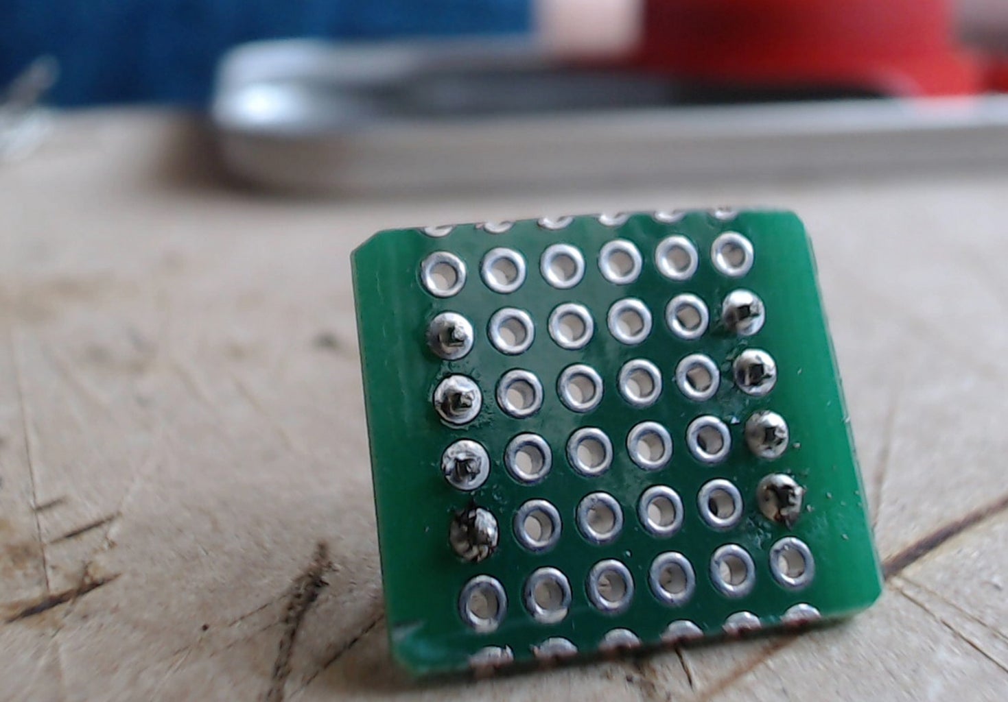

When you are happy withThis will help you later to add some wires. Don’t fill the holes that take the socket pins.the pins positions, start filling up the holes with solder.
Step 5: More Tracers

I used resistors, but you can use any wire to link the correct prototype boards. You can also use solder itself if you skilled enough. Start with the outer pins. Take a piece of the wire and solder it to a pin, bend it to required position and solder it to a hole. Repeat it with each pin. Take extra caution when soldering pins that will connect to the socket directly. Try not to flood the pinhole, but leave some solder on the end of the wire. The solder will melt when we start soldering the socket pins.
Use multi-meter (or a LED circuit) to check for shorts on each pin.
Step 6: Installing the Socket

Mount the socket, if you have flooded the mounting pins, use an iron to warm the solder up and push the pins through. Once the socket is secured, make sure you use plenty of solder to fill in the pin holes. They should melt the solder for sockets 1-2 and 7-8.
When the socket is in place you should have a sockets 1,2 and 7,8 connected. Confirm it with a multi-meter, make sure there are no shorts on other pins.
Step 7: Connecting the Socket

Wire up sockets 3,4,5,6. Use extra wires if you need to. Use the same technique. Start from the socket pin, and finish on the pinhole. When done, test all of the pins with the multi-meter.
Step 8: VCC - CH+ Short


We have to short two pins together. This will also decide about the orientation of the board. Use a spare jumper wire to select the VCC and Chip Power sockets, and identify the pins. Use extra wire to connect the pins on the surface. Make sure the wire won’t touch other traces.
Step 9: Nearly Over - Label

When all the soldering has been completed, verify that there are no shorts again (apart from Chip Power and VCC). It’s time to label the adapter. I used a piece of paperboard cut to size. Use hot glue to secure the board, and prevent the Chip Power – VCC from touching other traces, then mount the pre-made paper label. It’s wise to make which side the ESP8266 should face avoiding mistakes in the future.
Fill in the sides with glue and remove the excess glue with a sharp knife. You can cover the edges of the paper with superglue to prevent it from splitting.
Step 10: Confirmation

Verify the sockets for shorts again. Just do it, you don’t want your ESP8266 flash adapter to ruin your WIFI boards.
It will take about 1-2h depending on your soldering skills, but it’s worth the effort. Swapping the boards for flash takes moments. Just remove the board, and slot the next one in, press the power button and you are ready to flash!


