

Introduction: Build and Code a MONSTER Musical Tesla Coil With a Microcontroller


CALL ME AT 8059157065 IF YOU HAVE QUESTIONS. I DON'T USE MY INBOX
Visit my youtube page for more projects: http://www.youtube.com/channel/UCksEFn8xaLP0z4rsiHa9zcA?feature=mhee
As the winter months come up, many will be forced to stay indoors… To many, this will mean playing scrabble with grandma, watching television, doing puzzles, and sitting around the house. Why not begin an awesome project to spice up those potentially cold, dreary nights with an amazing light show decoration?
In this instructable, I will detail how you can do just that in creating an Audio Modulated Solid State Tesla Coil. Quite a mouthful isn’t it? For those foreign to the electronics engineering field or who simply just have no clue what “audio modulation” or “tesla coils” are, essentially what this device will do is produce visible streamers of electricity into the air (“lightning bolts”) pulsed at frequencies that correspond to audible tones (the device will “turn on and off” so quickly that the vibrations that the streamers make with the air sound like different notes). As we will see, we can exploit this neat effect to have the device play music and control it from behind a computer. So far, the secrets behind how these devices that sometimes make appearances on tv shows and movies has been kept under wraps and exclusively within the electronics engineering and computer science community or for very dedicated hobbyists putting in hours of research. In fact, for many high classes in elite colleges, n00b engineers would even have trouble making this on their own! This project could also be used to FREAK THE LIVING DAYLIGHTS out of people on Halloween! This year, I finished the project just in time to have this prop set up to play an eerie tune and trick-or-treaters were mesmerized (goes great to decorate a Frankenstein set).
This project is not for the light-hearted and is very difficult, but when completed, is extremely rewarding (it took me 2 years to learn how to build and finally do it). Not only will one learn loads about electronics and computer science, but simply taking this device to an event or (safely) to a public space rarely fails to produce a crowd of people taking pictures, impressed with your wizardly h@x0rz skills. Certain types of light bulbs or sticks will magically turn on without any wires. Good skills with power tools, machining, carpentry and the like are essential for crowd appeal. You have been warned, however, that there will be much tweaking, experimenting, and required dedication. In addition, be smart when operating tesla coils around sensitive electronics or in areas occupied by many people (basic common sense, I don't think there's much of a need to babble on, but if you are unsure, please work with an experienced engineer).
Step 1: What Is a Tesla Coil?


A tesla coil is a resonant air core transformer system invented by inventor Nikola Tesla in the 1890’s. Originally, tesla coils were designed to broadcast electricity and signals wirelessly, however, several engineering and monetary setbacks prevented the tesla coil from becoming the popular mode of energy transfer, and a power distribution method architecture relying on use of power grid lines (wires/cables) became the prevailing and accepted method. Now, tesla coils are primarily used for short-range wireless power transmission, for lighting up some types of lights, and for presentation/entertainment purposes.
Before going on, it is important to understand the basic functions of the primary components that make up our tesla coil and are used to make it (yeah, I know it’s redundant for most of you and most of you know how these parts work, but this instructable is for people from almost all backgrounds of experience):
Capacitor: Stores electrical energy and then releases it in short pulses (a little bit like a battery).
Transformer: Converts a lower voltage to a higher voltage (but makes output amperage go down) or converts higher voltage to lower voltage (making output amperage go up). Usually consists of coils of wire wound around a chunk of iron. The ratio of turns (how many times wire is wound around compared to other coils on the same chunk) of the coils determines how much voltage is increased our decreased. For there to be an output, a transformer must be fed AC (alternating current). In a tesla coil, the wires are not wound around a chunk of iron (and thus a tesla coil is sometimes called an “air core” transformer). In the tesla coil we will be building, a transformer such as a neon sign transformer is not required!
Transistor: Used for switching signals/voltage on and off. “IGBT” transistors are most commonly used, but require heat sinks.
Operational Amplifier: Used for increasing the amplitude (the “strength”) of a signal.
Tesla Coil Toroid: A metallic (usually made of aluminum) doughnut-shaped object with a small amount of capacitance (acts as a capacitor).
Microcontroller: Like a mini computer that can be programmed to perform a task.
Oscilloscope: Used to view what an electrical signal looks like (voltage over time graph).
Resistor: If put in a circuit it resists passage of electricity much like friction resists the passage of a moving object.
Potentiometer: Acts like a resistor but how resistive it is can be controlled with a little knob.
Inductor: Coil of wire that produces an electromagnetic field when electricity passes through it.
Rectifier: Takes Alternating Current and converts it to Direct Current.
Vector Board/Bread Board: Boards used for prototyping circuits. A breadboard does not require soldering to make connections, parts are just “plugged in.”
Ground: Usually denoted by a green wire, something connected to ground completes a circuit. Think of a lightning bolt moving from a cloud to the ground. In a similar way, electricity in a wire is attracted to and moves towards a ground connection.
Amps: A quantity that helps describe how much energy/power passes through something. Circuits in themselves typically have a limit to the amount of current that can pass through them and no more. A good way to think about it (though by no means is this a “scientific” definition) amperage tells you how concentrated the electricity is. In a welder, for example, amperage is very high because high concentrated energy produces a lot of heat.
Volts: This is also a quantity that helps describe how much energy that passes through something, but what it means for you and me is that it is a way to quantify how readily electricity “jumps” from one spot to another. HIGH VOLTAGE is characterized by the long electronic arcs coming from the tesla coil (typically over 100,000 volts). Electricity coming from the outlets in your house does not behave like this because the voltage is a lot lower (typically around 120 volts). A tesla coil steps the voltage way up, but that doesn’t mean that it just produces energy from nowhere. When voltage goes up, amperage goes down. When amperage goes up, voltage goes down.
Watts: A way to quantify total energy (combined voltage and amperage).
Check here for basic schematic symbols (we will need this later): http://library.thinkquest.org/10784/circuit_symbols.html
The operating principle behind a tesla coil is somewhat simple. Energy is sent to charge up a capacitor or set of capacitors. At a certain point, the capacitors are forced to discharge into the primary coil. When the energy that is stored in the capacitors is sent through the primary coil, a large amount of energy is induced (“sent”) into the secondary coil (alternating current is basically just electricity that changes voltage. When the capacitor fires, voltage changes from essentially zero to something really large in a very short amount of time). Since there are more turns in the secondary coil, the induced energy has a higher voltage, but a lower current than in the primary coil. The capacitors recharge and start this cycle again.
The capacitance of the capacitor and the inductance of the primary coil determine how quickly this cycle occurs per second and is measured in units of frequency called hertz. If a tuning fork vibrates at a certain frequency and another tuning fork that, if you hit it, would vibrate at the same frequency were put near each other, then simply striking one tuning fork would make the other start vibrating too. Why? Because of resonance. Tesla coils can be said to behave similarly; if the frequency of the primary circuit matches the resonant frequency of the secondary circuit, then the tesla coil is optimal, and like a tuning fork, energy will go from one part (the first “fork”/primary circuit) to the other (the second “fork”/secondary circuit).
In the olden days, capacitors would be charged up and a gap of metal would be put to each of the capacitor’s leads. When the capacitor was fully charged, a spark would arc inbetween the gap, thus forcing the energy into the primary coil. After the spark occured, the air inbetween the gap would be ionized. Ionized air acts sort of like a wire; electricity can move freely through it. Until the ionized air dissipated, energy would oscillate (move back and forth) between the capacitor and inductor many times. Instead of using spark gaps, we will be using transistors which are like little switches, but are controlled electronically. Turning the switch on and off quickly at certain frequencies will make the “lightning” coming out of the tesla coil make audible tones.
Keep in mind that even though we are turning the tesla coil on and off at a certain frequency (a certain number of times per second), its primary circuit is still oscillating (energy moving back and forth between the capacitor and primary coil a certain number of times per second) at a different frequency that we will match with the secondary circuit.
I have attached a simplified diagram of the basic way that we will hookup the tesla coil. This instructable is designed to be very flexible and allows for you to be your own designer through giving you the tools and basic knowledge needed to build one yourself from scratch.
Step 2: Overview


Suggested/Required Materials:
Oscilloscope
Computer
Assorted PVC Pipe
Aluminum Tape
Aluminum Ducting
Wood
Speaker Wire/Thin/Thinly Insulated Wire/”Magnetic Wire”
Thicker Wire
HV Capacitors
Toroid
Misc. Wire
Speaker (ripped out of a toy or a “happy birthday” talking card, etc.)
MSP430 Microcontroller
Soldering Iron + Solder
Operational Amplifier
Assorted Resistors
Assorted Potentiometers
Vector Board
Project Case
Switch
Breadboard
Screws
Male/Female Jacks
Bridge Rectifier
Power Transistors
Heat Sinks
Conductive Cooling Paste
Glue
Varnish
Saw/Something to Cut Wood or Plastic
Drill
Fuse/Fuse Holder
Breaking it into Parts
Building a tesla coil is easier once one breaks building it into a series of parts, and I will explain how things basically operate as necessary along the way. I have divided the task into the following parts:
Step1.) Designing Inductor/Capacitor Circuits and the Toroid:
In this step, (to avoid mathematics that intimidate the average layman from participation) we will use computer programs to help us approximate the size and parameters of our parts so we can build them.
Step2.) Building a Base:
In this step, we will build a base/case/stand for our tesla coil from wood or other available materials.
Step3.) Building the Secondary Coil:
In this step we will take some PVC pipe and wind a bunch of thin wire around it. The size of the PVC pipe, the number of windings, the size of wire all depend on what was determined in Step 1.
Step4.) Building the Toroid:
In this step we will need to make the metallic doughnut. There are several ways to build one that I will highlight, but the dimensions will depend on what was determined in Step 1.
Step5.) Building the Primary Circuit
In this step we will do something similar to what we did in Step 3, but we will use thicker wire and there will be less turns. There are many possible designs for primary inductors that I will highlight. A high voltage capacitor will be in series with the primary inductor. The voltage of our capacitor and the design of the primary inductor will have been determined in Step 1.
Step6.) Building the “Bridge” Switching Circuit
In this step we will build a circuit that can make the tesla coil when to switch “on and off” much like a switch, except solid-state.
Step7.) Programming the Microcontroller
In this step we will program a microcontroller to create a signal that will go into the switching circuit. Essentially, the microcontroller turns the switch that we build on and off. Programming will consist of modifying the signal so that not too much energy goes through the switching circuit over a given amount of time (otherwise it will fry the parts) and of converting songs into code.
Step8.) Amplifying the Microcontroller Signal
In this step we will amplify the signal from the microcontroller with an operational amplifier so that the signal is strong enough to trigger the switching circuit.
Step9.) Tweaking, Persistence, and Troubleshooting
Tesla coils are very finicky RF devices, and thus do not expect huge streamers right away. In fact, most tesla coilers spend years and blow many parts before they develop a really solid design. Adhering close to models and getting good parts will minimize frustration.
Step 3: Step 1 - Designing Inductor/Capacitor Circuits and the Toroid


You will need to download WinTesla here: http://www.mediafire.com/?si016unn6lt2qb0 (or ScanTesla works too). This is a good tesla coil modeling program that I have personally used in the creation of some of my coils and seems to work pretty well. Depending on available supplies, how large you want to build your coil, personal preferences, and your budget, you will want to plug values into the program to come up with ideal sizes for your secondary coil (diameter, length, guage, turns, frequency, etc.), for your capacitor, and for your topload (toroid). Do not worry about other parameters such as transformer and spark gap-related inputs. There are three different types of primary coils; a flat Archimedes spiral coil (“pancake” coil), a vertical cylindrical helix coil, or an inverse conical saucer. Whatever you choose does not matter, but have an eye for design and keep in mind that you will most likely be doing tweaking along the way to optimize your coil. If this is your first tesla coil project, I highly recommend first designing a small (maybe even handheld) tesla coil. This will lessen the pain associated with potential first-time false starts and the cost of mistakes. The main idea behind this step is to determine an ideal size for your coil.
If parameters are mismatched and the tesla coil isn't built correctly, it will be "out of tune." I have attached 3 pictures of different toroid sizes. Notice that if the toroid is too small or too big, the streamers aren't as long.
Step 4: Step 2 Â Building a Base


Now that you have a basic set of measurements for the primary coil and secondary coil, you will want to construct a base. I have done many different base types. Typically, bases are made of either wood or plastic. Both wood and plastic sheets are typically available at a nearby home improvement store. Generally, a larger base is required when designing a coil with a “pancake” type primary coil, while a smaller base is required for helical/cylindrical primary coils. Make sure that there is enough space under the primary coil in the base to put components (the capacitor and the switching circuit). In one of my designs, I screwed a plastic toilet flange to the base of the coil so that I would be able to remove my secondary coil whenever I needed to (remember, you will most likely be doing tweaking throughout the project, so you want to make things as modular as possible); the PVC pipe-based secondary coil fit snugly inside of it.
You will want to add a connector to connect the bottom of the secondary coil to ground. I drilled a small hole near where I was to insert the secondary coil and slipped a wire with a connector through it and then glued the connector in place, then under the base I connected the other end of that wire to ground.
Step 5: Step 3 Â Building the Secondary Coil


Take some PVC pipe and tape the end of a string of wire to the end of the pipe (make sure the PVC pipe is cut to the length determined in step 1, but leave a little extra space just in case). Now it’s time to start coiling! You will need to wrap the thin wire that you have selected in step 1 around the PVC pipe (yes, you will need to count the turns). It will be a very tedious task, but don’t get lazy here, and be careful to not let wire kink. When you are done and the wire is wrapped tightly, you may wish to put a layer of varnish around the coil to protect it (though it is not necessary).
Leave a good length of wire extending from both ends of the pipe so that you will be able to work with it. With my first coil, I attached a male spade connector to each end so that I could unplug the secondary whenever I needed to. You can take a lighter to burn off the coating on speaker wire or magnetic wire and then wash the ends to make good connections. A varnish coating is not necessary, but leaves a nice, shiny, protective coating.
NOTE: the secondary coil should have wire that has an insulative coating, otherwise the tesla coil will not work. Speaker wire and similar wire types should be fine.
Step 6: Step 4 Â Building a Toroid


There are many ways to build a toroid, but essentially what is desired is a metal donut. One method for producing this donut is to buy aluminum ducting of the desired width, then bend it and wrap it with aluminum tape. This will work, but might look a bit tacky (I did this for my first coil). Some tesla coilers have tried wrapping inner tubes with aluminum tape or using paper mache (or just buy one online). Of course, for that undeniable flashy clean look, you might have to fork over some cash and buy a premade one on ebay (but that’s cheating!).
Step 7: Step 5 Â Building the Primary Circuit


The primary circuit consists of high voltage capacitors in series/parallel to produce the desired voltage and capacitance. These have to be HIGH VOLTAGE capacitors (around 20,000v is good), and from my experience, CDE capacitors (specifically, model CDE 942C20P15K) work pretty well. Capacitors in parallel have an added capacitance, so for a higher desired capacitance, put multiple capacitors of the same type in parallel. Your tesla coil will only be as good as the capacitors you use, so I highly recommend purchasing them (they are pretty cheap, reliable, and worth buying).
In my first coil, I didn't need the switching circuits because I used a spark gap instead, so after I had the primary and secondary circuit hooked up, I just added a motor that touched the spark gap wires together at regular intervals and I was done! Doing this is a good way to make sure that your tesla coil is build correctly.
Step 8: Step 6 Â Building the ÂBridgeâ Switching Circuit


Perhaps the trickiest part in building a solid state tesla coil is the “bridge” or “switching” circuit. The bridge switching circuit is the heart of the modern day tesla coil and is responsible for taking in a signal and switching large amounts of power on and off very quickly based on that signal. The transistors (“switches”) that are most commonly used are called IGBTs or sometimes MOSFETs are used (Insulated Gate Bipolar Transistors). Ignoring all of that technical jargon, IGBTs are ideal because they are generally good at switching at speeds needed for good coil operation and can handle large currents. Before good transistors, there was no electronic switching circuit at all, but just a gap in the wire called a spark gap or a rotating wire that would fire once the capacitor was filled or when the wires got close enough (because the voltage built up and eventually could leap across the gap). This is very inefficient, but if this is your first tesla coiling project, I recommend first using spark gaps and using a high voltage neon sign transformer as an input to the primary circuit instead (however, this does not allow for audio modulation). Before electricity is sent into the bridge circuit, it needs to be rectified with a rectifier rated for the amps that your coil uses (pick something high).
TRANSISTORS
Since IGBTs switch such large amounts of energy and are so small, they have a high tendency to die or blow. For this reason, do make sure that IGBTs used are properly fastened to heat sinks of adequate size (though do not have the metal parts touch it). I have recently used IXYS SS1040 IGBTs.
4hv.org recommends these model IGBTs for use in tesla coils:
HGT1N40N60A4D
HGT1N40N60A4
FGA40N60UFD
FGH30N6S2
IRG4PC50UD
Use the attached diagram to help determine which metal terminal on the transistors goes where. Find out which terminal is what (collector, base, or emitter) for your specific IGBT model.
THE BRIDGE
DO NOT BE INTIMIDATED! Circuit schematics may look scary, but it really is just a way of graphically representing what goes where. Remember, you can use this link to help determine what symbol means what: http://library.thinkquest.org/10784/circuit_symbols.html
Half Bridge switching circuits use less IGBTs, but do not switch as much power as Full Bridge (H-Bridge) circuits. Similarly, Half Wave rectifiers do not convert as much AC power into DC power as Full Wave rectifiers. You will want a Full Wave rectifier, but do connect a fuse to the mains in order that your tesla coil does not draw too much current and then subsequently blow IGBTs as readily.
I have attached 2 simple schematics of how the two types of bridge circuits are wired in their most basic configuration, however, that is without important modifications to make your coil more failsafe.
There are several plans for bridge rectifier circuits online that have been tested and are reliable, and if this is your first time using switching circuits, I recommend first using them before trying to design one yourself, however, if you are adventurous and/or even know exactly what you are doing, expect hours of testing and work with an oscilloscope. I HIGHLY recommend starting out with a half-bridge circuit before moving on to a full-bridge. That is what I did with my first tesla coil, and it was difficult enough replacing 2 IGBTs when they blew, let alone 4!
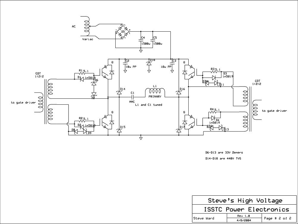
Check http://www.richieburnett.co.uk/sstate.htmlhttp://stevehv.4hv.org/drsstcdesign/ISSTC_sch2.JPG for free plans from other tesla coilers. Notice that the big part in the middle of Steve Ward’s plan looks a lot like the full bridge diagram photo that I have posted. In fact, it is a full bridge, except with a few modifications to protect the circuitry. I’ll talk a little about that.
CIRCUIT PROTECTION (DO NOT SKIP THIS!)
Diodes let electricity in one way, but block it in the other direction. This is very useful in protecting circuits from failure. TVS diodes (transient voltage suppressing diodes) are used frequently. Remember, IGBTs and transistors are very delicate, so it is best to have as much protecting them as possible. Notice in the schematic at the second link that diodes are placed between the transistors to ensure that voltage does not go where it is not supposed to. Use the schematic as a reference to design your own circuits and for good places to put your diodes. P6KE and SK07 (part number) diodes are pretty good for general protection. They should be rated around 440v and 600w. Keep in mind that since diodes let electricity go in one way and not the other, the way that they are oriented is very important. There is often a stripe on diodes that indicated polarity that corresponds to the little diode arrows in the schematic.
Capacitors can be used for making voltage graphs more clean or smooth and help absorb unexpected voltage changes. Like we did with the diodes, use the schematic as a reference for building your own circuit. Notice that two large capacitors are placed after the bridge rectifier (these are not high voltage).
Step 9: Step 7 Â Programming the Microcontroller


SETTING UP AND TESTING THE MICROCONTROLLER
Now it’s time to use your 1337 (elite) hacking skills to interface your tesla coil with your computer from scratch.
This step, for the first time ever in tesla coiling history, provides a direct and easy way for average hobbyists to build and tinker around with their own music board. Coilers don’t typically go into detail with this step because they assume that if you get up to this point, then you probably don’t need detailed instructions (plus it’s pretty cool, so why just give instructions away for free?). I produced this music board because I did not just want to buy one of those ones floating around online (they were $200 when I was looking!).
The microcontroller we will be using is the MSP430 Texas Instruments microcontroller. Why? It is really easy to use, and, unlike arduinos and the like, is dirt cheap (whereas arduino is more like a general “everything is here” board, the MSP430 is more specific, we just get what we need and won’t have to pay too much; it is around $5).
You will need to install Code Composer studio for your MSP430 in order to load codes to it. Specify a folder that you want to work in, and start a new project called Muzak. Follow the instruction book that comes with your MSP430 to do this. Once you have Code Composer Studio, download these files and/or copy and paste their code (this will require opening the .rar file): http://www.mediafire.com/?oogn9t59vvk4p2b
Put Muzak.h into your project folder. This file contains a table of notes that you will need.
Put Muzak.c into the “private” folder. This file contains code that specifies pulse width, clocking, and frequency information.
Put Main.c into your project folder. This file contains general instructions to the microcontroller.
Put Song.c in a new folder in your project folder called “songs.” This file is a music file that your microcontroller will play.
Put Rest.c in that same folder. This file is a music file that is empty.
What this code does is put a signal through pin P1.0. Once you load the code onto the board, you should see the red LED (light) blinking. This is because the music signal is sent through the LED and thus it blinks along with the song. To hear the song, remove the jumper across pin 1 hook up two wires from a speaker to P1.0 and Ground. You should here the song playing. Do you recognize it?
MODIFYING TO FIT YOUR COIL
Look at the signal through an oscilloscope.
The signal for “on” is when the voltage reaches past a threshold voltage (the top part of the square wave). Don’t worry about the threshold voltage yet, because we will be using op-amps to increase the amplitude of the signal. But basically the top part of the square wave is “on” and the long bottom part at near 0 volts is “off.” When the coil is “on” energy flows freely into the primary circuit. A good analogy is an everyday playground swingset; imagine that swinging one way represents energy going into the capacitor and swinging the other way represents energy going into the inductor (primary coil). When you swing, energy goes back and forth, but to go back and forth requires that you begin pushing the swing. When energy flows into the primary circuit (the “on” stage) is analogous to someone pushing.
I know you really want to, but you can’t just simply plug the music board into the tesla coil. You have to adjust the signal’s PULSE WIDTH, FREQUENCY, and DUTY CYCLE. If pulse width is too high, then too much power will go through the IGBTs at once and they will blow. Similarly, if pulses go through the IGBTs one after the other too quickly, they will also blow. Finally, if the IGBTs are on for too high a percentage of the time (duty cycle) then they will overheat and/or blow. The key is to keep pulse width, frequencies, and duty cycle low, then to gradually increase them to see what they can handle or cannot handle. In my coil, I limited (absolute maximum) my pulse width to 200uS (microseconds), the frequency to around 150Hz (200 pulses per second), and around a 2.5% duty cycle (it can be on 2.5% of the time). Don’t expect anything much higher for your coil! Digital oscilloscopes (if you do not have one like me, see if you can use someone elses at a computer lab, college, or at a friendly engineer’s house) have the advantage that they measure all of these for you.
Adjusting the code will allow you to adjust all of these parameters. Open Muzak.c. There are variables near the top labeled specifically for you. Change their values and see what happens to the output waveform. You can also edit Main.c to give your microcontroller general instructions. Currently, the two instructions in the file are:
playSong(); <- this plays the song
and then
delay_ms(0); <- this tells the coil to rest for a certain amount of time before the song repeats
After you have adjusted the code, check the output waveform using the oscilloscope and continue modifying until you get a desired output that you feel good will work well with your coil (start low first!). Years ago the first time I experimented with audio boards my frequency was way too high, and so my tesla coil blew (plus the audio quality wasn’t that great because at the time, my H@x0ring skills weren’t 1337 so I wasn’t coding songs, I was just using electronics circuits to modify audio output from any mp3 player (it was “analog” instead of “digital.”).
CODING SONGS
I have included a few song instructions here: http://www.mediafire.com/?t48qa78eoplx760, but if you would like to code your own, I will explain briefly how. In my High School java class, we programmed a fake robot and gave it a list of instructions. Essentially, coding music works the same way; you are giving your tesla coil a list of instructions on what to play. The code that we are working with is similar to java code in that it is object oriented.
Download Anvil Studio and a .midi file of your choice. Open the .midi file using the program. You will be given a graphical representation of the song of your choice, and you will see which notes play when and for how long (this is a good reference). This is all of the information you need to code a song! In the code there is a table of notes that I have pre-coded in, so all you have to do is specify a list of notes that will play in your song in succession, and for each note, specify the duration it plays and insert rests. After a few attempts and testing, you will find that eventually your coded song will begin to resemble what you would like. You can play around with making your own songs until you are satisfied.
For example, in Song.c the instruction beep(G1H, 120); tells the microcontroller to “beep” with a note G1H for a duration of 120 units of time (determined by the microcontroller’s clock speed). The note “R” is a rest.
You cannot have your song too long because otherwise you will run out of memory. In addition, these tools show you how to make a monophonic tesla coil audio board, and so, in other words, you can only play one note at a time.
Step 10: Step 8 Â Amplifying the Microcontroller Signal


Now that you have basically everything put together, we can’t usually just hook the tesla coil’s bridge circuit up to the audio board and go. It’s not that easy, see, you have to make the amplitude of the signal above the IGBTs’ threshold voltage. In simple terms, you have to make the signal bigger so that it is strong enough to trigger the IGBTs. To do this, we can use something called operational amplifiers (“op-amps.”).
An operational amplifier is a little chip that we can hook up to a power source like a battery and use the power to make the input signal bigger. We use resistors connected in a certain way to control how much the signal is amplified (called “gain”). We learned earlier that potentiometers can be used just like resistors, except that they have a little knob that allows you to control their resistance without having to put in a new resistor each time you want to change the gain. Using a potentiometer you can simply turn the knob until the IGBTs are triggered (if everything is working correctly!). Some operational amplifier chips that I have used are the LM741 or the MC1458CP. These helped me step up the voltage of the signal from around 3 volts to around 9 volts (300% gain).
For beginners, op-amps can be a bit daunting because of the way that they are represented in diagrams (weird arrows…what’s going on?). However, all you have to do is know which part of the diagrams means what. I have included some pictures that help alleviate the confusion.
Remember, you will need to look up which pin is what on the specific op-amp model you will use. You will need to locate which pin is V+, V-, IN-, IN+, and 1OUT, then use the pictures to build the circuit. I used a 9 volt battery for my op-amp, and connected the minus terminal to ground.
The ratio of the resistor that is connected to the input with the resistors connected to the output determines the gain, so using a potentiometer instead of a resistor of constant value is useful. For my op-amp, I connected a 10k resistor to the input and two 1k resistors to the output.
Along the way you might want to check the oscilloscope to make sure that your op amp is correctly amplifying the signal.
Step 11: Step 9 Â Tweaking, Persistence, and Troubleshooting

If you thought that the last step was the final step, think again. After hooking everything up, you WILL run into problems. Even for professional and experienced engineers, things usually do not work the first time around. In fact, this project took me a couple years to perfect. If your tesla coil is not operating correctly:
Check to make sure things are connected in the correct way
Make sure that you have circuit protection
Check to see if diodes are working correctly or if the IGBT/MOSFETs have broken
Make sure that IGBT/MOSFETs are fastened to a heat sink and aren’t getting too hot
Lower the pulse width, frequency, and/or duty cycle
Use a variac to slowly give power to your tesla coil
Contact other tesla coilers on 4hv.org with a specific question or seek outside help or research
Use an oscilloscope to tweak circuits until you get the desired waveform
Make sure that the frequency of the primary circuit is resonating with the secondary circuit. To do this, use a clamp to move the connection on the primary coil
Try using a breakout point on the toroid (connect a sharp metal point to the toroid such as a bent paper clip)
Make sure the fuse hasn’t blown
Use a speaker to see if the music is coming from the audio board
Make sure your connections are solid and not flimsy
Make sure your circuit does not look like a rat’s nest. That is not good.
Good Luck! And if you find this instructable informative, please don’t hesitate to vote for me, like, rate, and share! Post your related projects or discuss ideas below.

Finalist in the
Make It Glow Challenge

Runner Up in the
Hack It! Challenge

Second Prize in the
4th Epilog Challenge

Finalist in the
Halloween Decorations Challenge


