

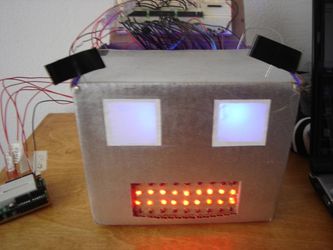
Introduction: Build an Arduino-powered Talking Robot Head!
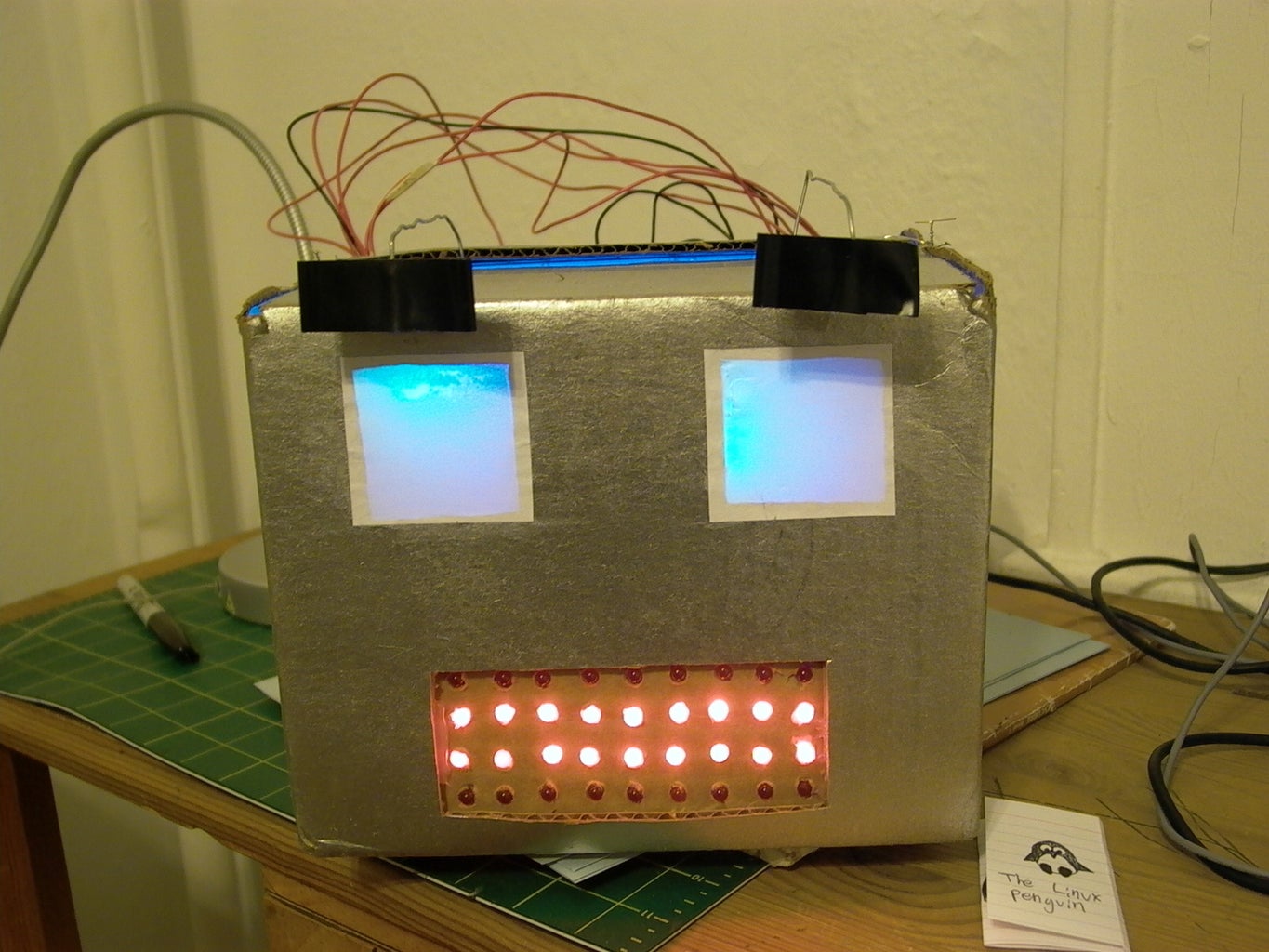


The head is powered by two Freeduinos, 3 TLC5940NT chips and an Adafruit Industries Wave Shield found here: www.ladyada.net/make/waveshield/. The head is currently connected to a computer by two USB cables, one for power, one for sending it serial commands on what to say/emote. Once the head receives the typed commands on what to say/emote it plays back the individual word files in order creating a sentence or multiple sentences. It also changes its emotions according to the emotional commands sent from the computer.
This robot head is a foundation for many possible applications since it can say anything that it has the vocabulary for. Right now I am currently working on connecting it to the internet and making it check and read my email via PHP script. I will update this Instructable as I progress along with that.
Here's a video of it in action:
The head is still an on-going project so any comments on anything here are more than welcome!
Special thanks to Liz Arum for helping me with everything!
Update: Due to popular request I now have now added a video of the robot talking and expressing itself! Enjoy at your leisure!
Step 1: Compile All Materials/parts/electronics.
This robot head uses:
1 Breadboard (It has to be more than 48 rows long with a gap running down the center of the board to connect IC chips. A power and ground bus running along the side of the breadboard is also a necessity.)
2 RGB Leds (For the multicolored eyes) Common Anode. $1.50 - 1.95 each. 2 X $1.75 = $3.50
36 Red Leds (For the mouth) somewhere around the 40-50 cent price range for each. 36 X $.45 = $16.20
2 HXT900 Micro Servos (For moving the eyebrows) Can be found at: http://www.hobbycity.com/hobbycity/store/uh_viewItem.asp?idProduct=662 2 X $3.65 = $7.30
3 TLC5940NT's (To drive/light up all the Leds and control the servos) can be found at Digi-key http://search.digikey.com/scripts/DkSearch/dksus.dll?Detail&name=296-17732-5-ND where they are priced at $4.28. 3 X $4.28 = $12.84
or Mouser http://www.mouser.com/ProductDetail/Texas-Instruments/TLC5940NT/?qs=sGAEpiMZZMu8%252bGBKj8XSFEjwsgnt5grMZ49G/W4nR14%3d
3 Capacitors (~1000uf) (for ironing out line noise from the Leds and servos) Salvaged from an old computer power supply. Free
2 Original Freeduinos or Arduinos. The Freeduinos can be bought at http://www.freeduino.org/buy.html They are priced at 23.99 each. 2 X $23.99 = $47.98
Or www.sparkfun.com/commerce/product_info.php for Arduinos. Priced at $29.95 each. 2 X $29.95 = $59.90.
Warning: The Freeduinos require some soldering knowledge, if you would like not to solder your boards then buy an Arduino.
Warning: This Instructable requires some soldering knowledge anyway, so why not start now? :)
1 Waveshield from Adafruit Industries (To allow the robot to talk) Can be bought at: http://www.ladyada.net/make/waveshield/ Priced at $22 each.
Estimated total cost of all high tech parts(not including shipping) if you bought Freeduinos instead of Arduinos is.... $109.82!
The total cost of all high tech parts if you bought Arduinos instead of Freeduinos is.... $121.74!
And as for the low-tech materials you will need:
A cardboard box the same size that you want your head to be.
A small piece of cardboard
Tape
Glue
Breadboard compatible wire (22 gauge, solid)
Wire for fastening stuff to other stuff
A small block of wood
Power drill.
Heat Shrink tubing for isolating the exposed wire leads and something that blows hot air to shrink it with (Hot air gun)
Box cutter.
Step 2: Assemble and Solder All Circuitboards and Shields.

Solder the Freeduinos (like I did), Or disregard this line if you bought a Arduino. Here is the link to their assembly instructions for all of the people who bought Freeduinos:
mcukits.com/2009/03/12/assembling-the-freeduino-board-kit/
Solder the Waveshields. Lady Ada has a very good guide on how to do this on her website at http://www.ladyada.net/make/waveshield/solder.html
Note:
In addition to soldering together the Waveshield as outlined. Add a long wire soldered onto the resistor R7 on the side closest to the amplifier chip. This will be connected to the Analog Input 1 on the Freeduino that is controlling the LEDs of the robot head. (Don't worry about where to plug the other end of the wire for now, that will be explained in detail later.) See the picture for clarification on where to solder the wire.
Step 3: Design the Robot Head.

Take the cardboard box that you chose to be your head and mark out the places that you would like to cut out for the eyes and mouth by cutting pieces of paper and laying them on top of your box. When you are happy with the arrangement you can move onto cutting stuff.
Step 4: Design Your Robot Head: Cutting the Eyes Out.
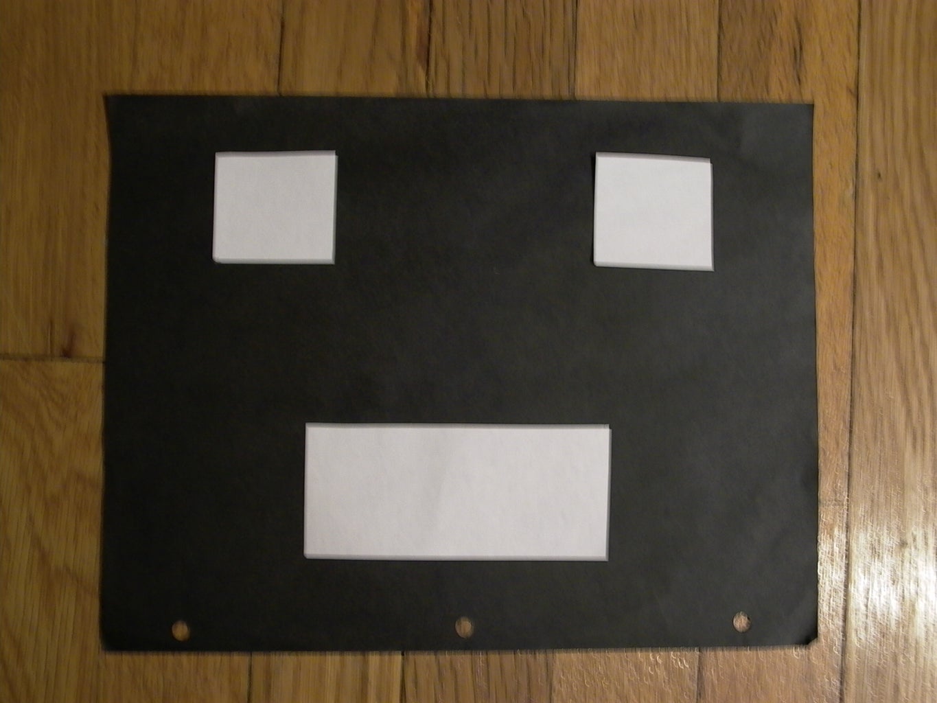
Tape or mark the pieces to their final positions onto the box and cut them out. (Keep the piece of paper that you used to represent the mouth, you will need it later.)
Step 5: Design Your Robot Head: Making a LED Matrix for the Mouth.


Each LED in the mouth will light up independently. To do that you need to make an LED matrix for the mouth. (For an idea on what is a LED matrix, see picture 1)
Take the piece of paper that is supposed to be the mouth and, with a pencil and ruler, Divide up the piece of paper into 36 parts (9 X 4), One for each LED in the grid.
After you have done that, tape the piece of paper to a piece of wood and being careful not to drill through the floor (This has happened to me so I recommend drilling on top of a cardboard box.) Drill holes where the lines intersect with a 1/4 inch drill bit, so that your LEDs fit snuggly. The size of the drill bit is obviously dependent on the size of your LEDs so use a smaller drill bit for smaller LEDs. (Start small and work your way up!) Look at pictures 2&3 for clarification on the drilling/marking.
Step 6: Making the Mouth LED Matrix: Soldering in the LEDs.


Before doing anything else, check that all your LEDs are not burned out or dim. You can do this by finding a small 3V button battery and holding the legs of the LEDs to the battery (Remember the long leg is positive, the short negative).
Next insert the LEDs one row at a time into your drilled out grid jig. Fold the long legs so that they are parallel to one another and solder them in, row by row (See pictures 2 & 3). Solder together the long legs since you will be using TLCs to control these LEDs, and the TLCs are power sinks. This means that they control the LEDs by altering the voltage differential between power and ground.
Step 7: Making the Mouth LED Matrix: Soldering Control Wires Onto the LEDs.


Solder long wires that can fit into a breadboard (22 gauge) onto all the LED cathode leads. These wires will control the LEDs. Afterwards be sure to insulate all the individual wires with electrical tape(not fun) or heat shrink tubing(recommended).
In addition to soldering wires onto all of the LEDs Cathode leads, solder 2 or 3 wires onto the Anode part of the grid (The part that is all soldered together). These wires will serve as power supples distributing power all throughout the grid. They will be connected to 5V.
Step 8: Install the Eyebrow-moving Servos Inside of the Robot Head.
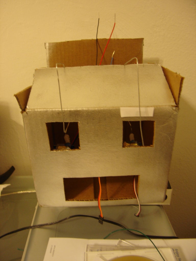
Before installing your mini-servos inside of your robot head, hot glue a long strong (But still bendable) wire onto the servo arm. This wire will go up the inside of your robot, come out of the top and creep back down to move the eyebrows. (See the pictures for clarification.)
Take your mini-servos (with the wires attached) and hot glue them to the inside of your robot head, right underneath the eyes, making sure that the wires can move from side to side.
Step 9: Install the Grid Inside of the Robot Head.


Hot glue the grid to a piece of cardboard that you have drilled holes in and hot glue that onto the inside of the robot head.
Step 10: Solder the RGB LEDs.

Solder the Common Anode RGB LED lead to a long wire. Then solder a colored wire (red, green, blue) to the RGB LED lead that corresponds to it (The color of an individual lead can be found out by using a 3V button battery to light each LED lead in turn). Don't forget to insulate the wires!
Step 11: Install the RGB LEDs Inside of the Robot Head.


Install the LEDs inside of the robot head by putting them where you want them and then folding and taping the wires to the inside of the box. Putting a drinking straw under the LED also helps to keep it in place. (See pictures for clarification)
Step 12: Finish Making the Eyes.

Glue a square piece of paper that is slightly larger than the hole that you have cut out. Glue it over the hole to cover up the hole and the LED behind it. You might also want to tape some sheets of paper towel to the inside of the eye holes to diffuse the light coming from the LEDs.
Step 13: Wire Up the TLC5940NT Chips.
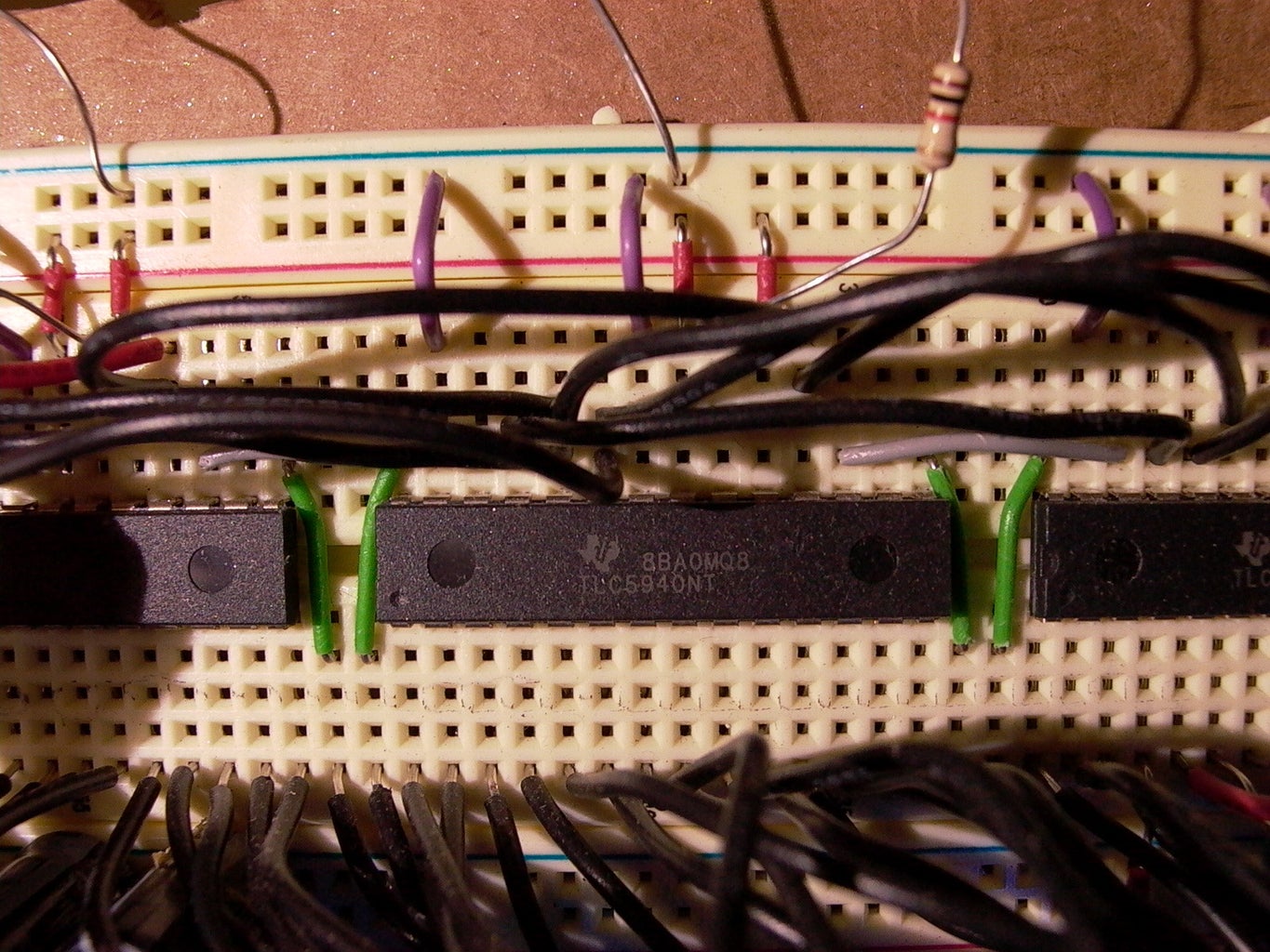

In this step you will have to daisy chain 3 TLC5940NTs together to drive a total of 42 LED outputs (36 for the mouth, 6 for the multicolored eyes).
The people at the Arduino playground have a very well documented hookup guide on how to daisy chain 3 TLC5940NTs together. Here it is in compressed form:
Arduino pin 13 -> SCLK (TLC pin 25)
Arduino pin 11 -> SIN (TLC pin26)
Arduino pin 10 -> Blank (TLC pin 23)
Arduino pin 9 -> XLAT (TLC pin 24)
Arduino pin 3 -> GSCLK (TLC pin 18)
--------------U------------
LED Out 1 | 1 28 | LED Out 0
LED Out 2 | 2 27 | GND
LED Out 3 | 3 26 | SIN (Ard pin 11.)
LED Out 4 | 4 25 | SCLK (Ard pin 13)
... | 5 24 | XLAT (Ard pin 9)
... | 6 23 | BLANK (Ard pin 10)
... | 7 22 | GND
... | 8 21 | VCC (5V)
... | 9 20 | 2K Resistor to Ground
... | 10 19 | 5V
... | 11 18 | GSCLK (Ard pin 3)
... | 12 17 | SOUT (Connected to the SIN of the next TLC in the Daisychain)
... | 13 16 | XERR
Out 14 | 14 15 | LED Out 15
-----------------------------
Note: we are Daisychaining 3 TLCs so the SIN of the first TLC is connected to Arduino pin 11. The rest of the TLCs have their SIN connected to the SOUT of the TLC preceding it.
All the BLANKs are connected to each other (BLANK of TLC1 is connected to BLANK of TLC2 etc...)
All the XLATs are connected.
All the SCLKs are connected.
All the GSCLKs are connected.
All the XERRs are connected.
Also plug in 2 or 3 Electrolytic capacitors to the breadboard's Ground and Power (Negative on the capacitor going to Ground, Positive to 5V). The amount of charge that it holds is not that important but it should be rated for 5V or above. These capacitors will act as a filter, filtering out all the imperfections(noise) in the voltage supply that the TLCs produce. This is important because the Waveshield that we will be using shares the same ground as the TLCs and REALLY doesn't like electrical noise (it makes a weird, clicking noise).
Step 14: Wire Up the LEDs to the TLCs

Connect all of the LEDs to the TLCs, row by row, starting with the one in the upper left-hand corner and moving on to the LED directly on the right. Here is a grid of all the LED TLC pin outs included for your convenience.
See pictures for clarification.
Mouth:
0 1 2 3 4 5 6 7 8
9 10 11 12 13 14 15 16 17
18 19 20 21 22 23 24 25 26
27 28 29 30 31 32 33 34 35
Now is also a good time to plug in your RGB LED eyes to the TLCs so here is the pin outs...
RGB LED eyes:
Left: R G B Right: R G B
36 40 38 37 41 39
Don't forget to plug in the universal power wires for The Grid and RGB LEDs into 5V!
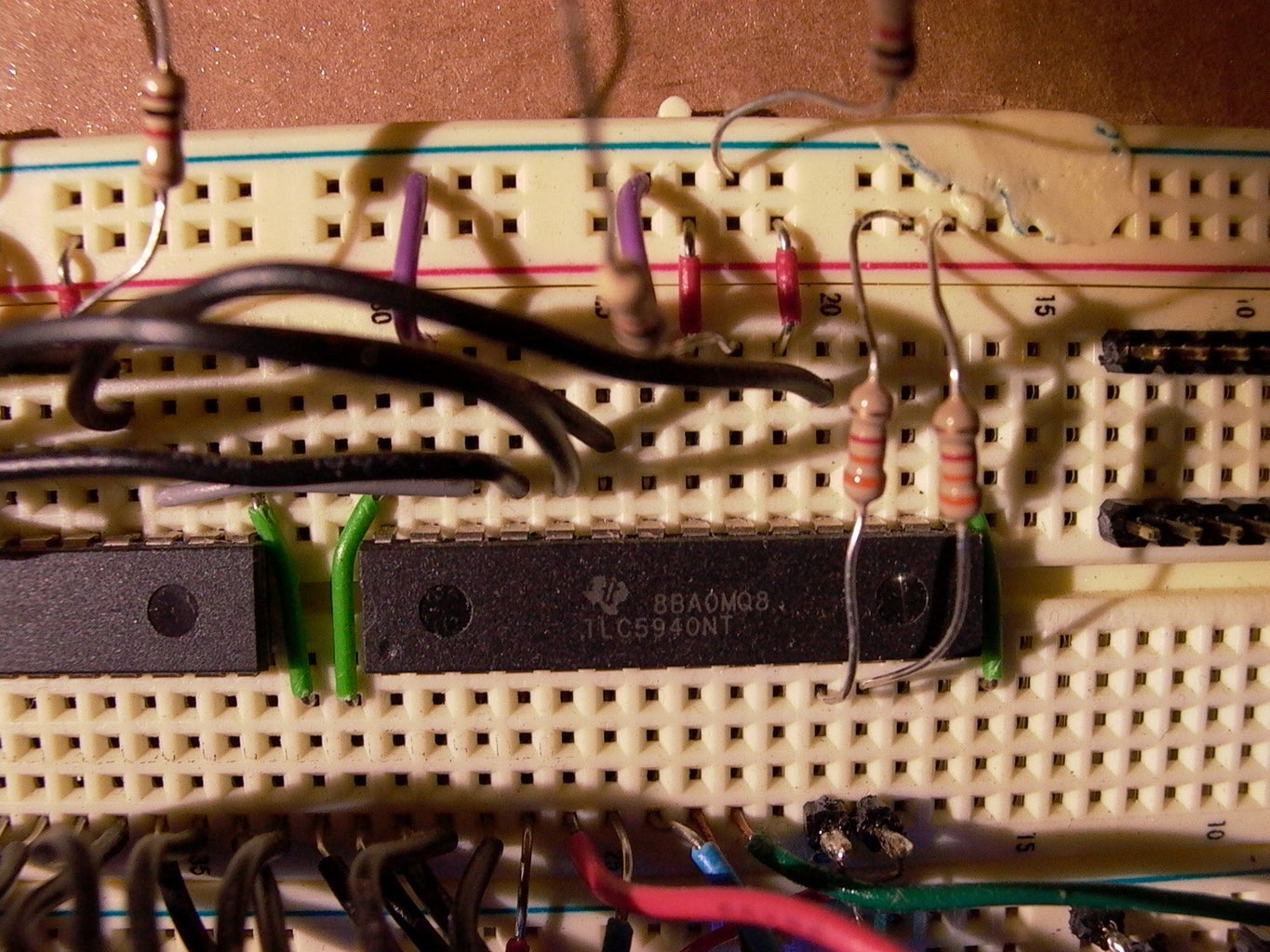
Step 15: Wire Up the Servos to the TLCs.

Connect the Power and Ground of the servos to Power and Ground on your breadboard. Connect the control wire of the Left servo (Your left while facing the robot.) to pin 43 (Remember start at zero.) and the Right servo to pin 44. You will need to connect a 3.3K ohm resistor from both of those pins to 5V because the TLCs are power sinks and require power to sink.
Step 16: You Are Now Entering the Land of Software and Code! (mostly)
Please no trespassing...
Step 17: Download the TLC Library.
The latest TLC library for the Arduino can be found at their Google code page at: code.google.com/p/tlc5940arduino/.
Download the latest library and insert the unzipped folder "Tlc5940" into [latest Arduino version folder]/hardware/libraries/
Step 18: Test the TLCs.
Load my serial expression test sketch which you can download below. Load it into the Freeduino and type some commands into the serial monitor to test that the whole thing works.
Here is the list of commands:
behappy
besad
bemad
fullmouth
linemouth
offmouth
offeyes
bluegreeneyes
redeyes
blueeyes
openmouth
talkmouth (It doesn't talk, but it makes mouth movements)
Attachments

Step 19: Download the Improved, High-capacity Supporting (Somewhat), Waveshield Library.
Download the new improved Adafruit waveshield from Google code (Thank you Mr Fat16 for making this improved library): code.google.com/p/wavehc/
Again stick the unzipped folder in the hardware/libraries/ folder.
Step 20: Format and Load Your SD Cards.
Insert your SD cards into your computer and format them using the FAT or FAT16 file type. NOT FAT32! Then load your SD cards with speech files from AT&T's great text to speech site www.research.att.com/~ttsweb/tts/demo.php#top Rename the files the name of the word that it is speaking in the file and truncate that file name to something that contains 6 or less letters. (The waveshield can only handle files whose filenames are 6 characters or less.)
Ex.
If you download the file for "Instructables.com" -> name it instrc.wav
If hello -> hello.wav
Step 21: Test Your Waveshield.
Download and run my serial Waveshield test sketch. You should be able to through the serial terminal, type a sentence and have the Waveshield play it (As long as it has the .wav files that it needs). It will take the first word, add the ".wav" and play it before moving on to the second one.
Ex.
you type: Hello my name is Bob
It will play:
hello.wav
my.wav
name.wav
is.wav
bob.wav
Note: Test the Waveshield on the other Freeduino (the one that is not connected to the TLCs) because both the Waveshield and the TLCs use pins13,12,11 and 10 (on the Freeduino). This is because these pins have hardware support for a interface called the Serial Peripheral Interface (SPI) that both the TLCs and the Waveshield require. These pins cannot be shared between them so we will have to link two Freeduinos together using the I2C interface so that they may pass information between them. More on this in step 22.
Step 22: Wire Up the I2C Interface Between Both Freeduinos.

Wait... Why do we need to wire up a I2C interface between two Freeduinos? Why can't we just plug the Waveshield and the TLCs into one Freeduino? Here's why:
Both the Waveshield and the TLCs use pins 13,12,11 and 10 on the Freeduino. The reason for this is that these pins have hardware support for a interface called the Serial Peripheral Interface (SPI) that both the TLCs and the Waveshield require and cannot share. This means that we will have to link two Freeduinos together using some sort of data connection so that they both work together in tandem. Serial was not an option because my computer was already using it to communicate to the Waveshield Freeduino, so after some intense Googling I found a remarkably convenient and simple communication method. I2C! Here is how to wire up the interface:
Connect Analog Input pin 4 on both Freeduinos (This is the SDA or Serial Data Line.)
Connect Analog Input pin 5 on both Freeduinos (This is the SCL or Serial Clock Line.)
Connect the Ground on both Freeduinos (Otherwise the I2C interface will not work.)
Connect the wire that you soldered at the beginning of this Instructable from resistor R7 on the Waveshield to Analog Input pin 1 on the TLC controlling Freeduino(This wire is for checking the volume of the words spoken by the Waveshield and is not part of the I2C interface). (See picture for clarification)
Step 23: Enable I2C on the TLC Controlling Freeduino.
Enable I2C on the Freeduino that you used to control the TLCs by downloading this sketch. It will receive information on expressions from the Waveshield and will also check the volume of the speech output on the Waveshield Freeduino and will move the mouth to simulate talking depending on the volume of the word being spoken.
I2C definition: I2C is also known as TWI (Two Wire Interface) it is a simple way of connecting multiple devices together (up to 128!) with two data wires and a common ground.
Update: I have added a blink feature to the Arduino Sketch. The robot will now blink at 2-11 second intervals, just like a human.
Step 24: Test the I2C Interface.
Download this sketch and load it onto the Waveshield Freeduino, it sends the words"behappy;" and then "besad;" over the I2C interface to the TLC controlling Freeduino at two second intervals, hopefully making the robot go from happy to sad at two second intervals.
Attachments
Step 25: Your Almost Done! Just Some Code to Load...
Load the final version of the Waveshield Freeduino code. It should take any words that you type into the serial monitor and speak them (as long as it has the .wav files to do it) and should pass expression commands like "behappy;" and "besad;" onto the Freeduino controlling the TLCs through the I2C interface.
Note: The command list is the same for the earlier TLC test code (See step 17) except that you must add a semi-colon to every expression command. EX.
If you want the robot to be sad and say "I feel sad" then type:
besad; I feel sad.
Update: The Waveshield Sketch now uses punctuation properly (i.e. periods and commas but notexclamation points).
Step 26: Mount Everything on the Robot Head Box and You're Done!
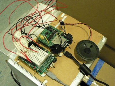
Mount all of the Freeduinos onto the back of the box with wires. Close the top flap of the box with wires and you're done! Now if only it could check my email. Hmmmm.......
Thank you for reading this Instructable! Comments are always welcome on anything!
Second Prize in the
Arduino Contest


