

Introduction: Build Your Own Wifi Radio


The internet hosts lots and lots of online radiostreams, most of them with a certain theme, ranging from old time classics to Tibetian riverdancing. I must admit that I love to listen to them while I'm building stuff, as I can choose the music I like without listening to the same cd's over and over again.
The only problem is that I always needed to have a computer neaby to get an internet connection. So I looked around to buy one, but they are quite expensive and besides that, it is a lot more fun to make your own.
As I had no clue at all about how to do the wifi and internet part of the project, I searched the net for clues and I stumbled upon www.mightyohm.com. This site belongs to Jeff Keyzer and he has an excellent step by step tutorial on it for hacking a wifi router into a wifi radio. If you follow his instructions, you will end up with a working radio but I decided to build my own graphical interface for it and my own case.
I really wanted this project to look as nice as possible, so I invested a lot of time in designing and building the case. I hope that this build is awesome enough to have a chance in the lasercutter contest or the makerbot contest as I would love to have one of these machines. They would allow me to make even nicer looking and more intricate cases and parts and I wouldn't have to bother my friends to mill parts for me ;) ( in fact I might be able to help them out then).
I would like to thank Jeff Keyzer for helping me with setting up the router correctly, Izaak for helping me with out with the CNC part and my wife for helping me with the veneer.
Step 1: What Do We Need for This Project?
First of all, we'll need an ASUS WL-520gu wireless router. This router will handle the internet connection and also play the music.
Secondly, we'll need a RS232 to usb converter (3,3V version). We will need that to hack the router. I used a couple of xbees to do this as they are 3,3V and a few wires less on my desk is always handy. If you don't have those you can buy converter cables all over the net (here for instance).
We'll also need a USB sounddevice. I used a creative SB0270 external soundcard that I had lying around for years but you can buy very cheap small thingies everywhere. If you're not sure whether the sounddevice you have will work, then you can go to the forum on www.mightyohm.com. There is a list there with working devices.
Amplifier
There are 2 options to make the sound audible. You can either use an external amplifier or you can use an internal one. I actually combined the 2 options. I used a kit (K-VOTI-003 on www.voti.nl) for the internal amplifier but I also added audio output (stereo cinch) on the back for an external amplifier. Ofcourse you can build you own amplifier too but I was a bit short in time
If you use an internal amplifier, then you will need some speakers too.
I also added a headphone connector to the front.
Interface
For the interface we'll need:
- Agraphical LCD: I used a monochrome 240*128 LCD (LCD-21 on www.voti.nl)
- An ATmega16 or 32: The size is depending on the amout of graphics you want to display. I used an smd version but ofcourse you can make your project with thru-hole components.
- A DS1307 Real Time Clock
- Battery holder + 3V battery: CR2032 in my case
- A 32.768kHz quartz crystal
- A rotary encoder: I used an alps encoder with pushbutton
- A 10K potentiometer
- A bunch of resistors: 3 x 1K5, 2 x 4K7, 4 x 10K
- BSS138: 2 x for the level converter
- Some male and female headerpins
- A connector for your programmer
- 3 double switches
- 5 led's
The Case
For the case we'll need a lot of 18mm MDF and some real wood veneer.
The front and the backpannel are made of alucobond which is a sheet of poylethylene sandwitched between two 0.8mm layers of aluminium.
We'll also need 5 holders for the LED's and a powerconnector.
Step 2: Hacking the ASUS Router


I won't go into much detail on how to do the hacking of the Asus WL-520gu, as it is fully explained on the mightyohm-website. You only need to follow it until part 5 because after that we'll build a different interface and case. Jeff Keyzer deserves all the credits for this part an I also want to thank him for helping me out with the problems that occured.
I'll give a quick summary here of the 5 steps:
Steps 1 and 2 are a general introduction but it is nice to read them as they contain some interesting information.
The fun begins in step 3! Void the warranty (Yay!!) by opening the case of the ASUS. When it is opened you need to locate where you can solder a 4 pin male header. It is located near the silkscreen ASUS logo. Soldering the headerpins was a bit tricky. Best way to do it is to remove all the solder that is in the holes before you even try.
In step 4, you'll install OPENWRT on the router. Follow this step very closely as it is possible that you break your router forever when you do something wrong. If you succeed in installing OPENWRT, you can continue with setting up your internetconnection in the second part of step 4.
In step 5 you will install mpd (music player deamon) and configure it. If you have completed step five, you should hear some music!
After completing these 5 steps, you can carry on with this instructable.
Step 3: Add an External Mpd Client

At this stage, you could close the router again and use an external mpd client to control your radio. In this instructable we will also build an interface but having a way to acces the player while testing is always good.
You can download a lot of mpd clients athttp://mpd.wikia.com/wiki/Clients, even for you Iphone. I downloaded and installed the Ario client. To do so, I needed to install GTK+ too ( http://gtk-win.sourceforge.net/home/index.php/en/Downloads).
When you have installed the program, you need to set up the connection. By host you add the ip-address of your router and by port 6600. When done click the connect button and you should be able now to control your radio from your pc.
Step 4: Building the Interface (hardware)
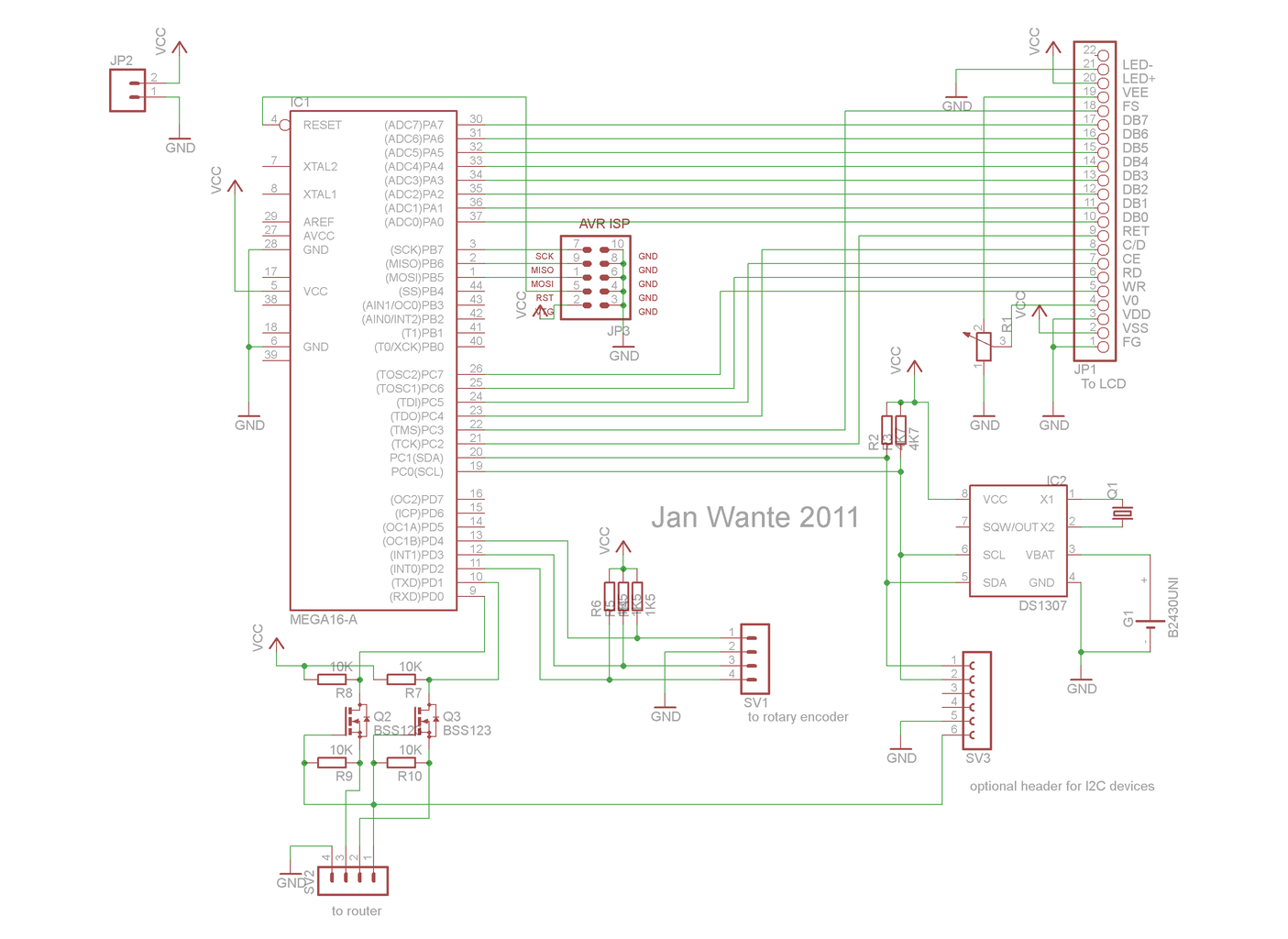


Building up the interface is not very difficult. It can be done on a piece of veroboard or you can make your own PCB.
Connect the LCD to the microcontroller
I would love to tell you what pins need to be connected to what but every LCD has it's own pinout. You can find the right way to do it in your datasheet.
When working with graphical LCD's, I'll always us port A for the data pins and the higher part of port C for the control pins. That leaves me portc.0 and portc.1 for I2C communications.
Don't forget to add the 10K potentiometer between Vee , V0 and Vss for brightness adjustment .
My LCD had an internal resistor for the LED so I just hooked it up to 5V and GND. You could ofcourse connect the LED with one of the PWM pins on your microcontroller to controle the brightness, but I didn't opt for that.
Connect the DS1307 to the microcontroller
Connect pin 5 of the DS1307 to portc.1 of the microcontroller ande pin 6 to portc.0. Don't forget to add the two 4K7 pullup-resistors to those lines. Add the crystal to pin 1 and pin 2 of the DS1307 and add the batteryholder between pin 3 (positive) and pin 4 (negative). Then hookup pin 8 to 5V and pin 4 to GND.
Connect the rotary encoder to the microcontroller
The pushbutton will have 2 pins on your rotary encoder and the encoder itself will have 3 pins. Connect one pin of the pushbutton to INT0 or portd.2 on the microcontroller and the other pin to GND. Then connect the middle of the 3 other pins to GND, one to INT1 or portd.3 and the last one to portd.4.
All the lines to the microcontroller need a 1K5 pullup-resistor.
Connect your microcontroller to the RS232 pins on the router
If you look at the pins on the router, you will notice that one of them is connected to a thick diagonal trace. That pin is 3,3V and lets call it pin 1. Pin 4 is GND, pin 2 is RX and pin3 is TX.
Connect RX to TDX on your microcontroller (portd.1) and TX to RDX (portd.0). But because our microcontroller needs 5V and the router 3,3V, We'll need a level converter. You can learn how to build one in one of my other instructables or you can buy one online.
Don't forget to add your programming link.
That is all we need to start programming the interface.
Attachments

Step 5: Setting the Baudrate and Echo
Before we can start to communicate with our router, we need to change its baudrate. The routers baudrate is 115200 and we want it to be 9600 (I was told that 19200 works fine too). Another thing we should change is the echo. Now the router echos back every charater that we sent to it and that would make our Uart-buffer a mess, so we need to turn that off.
I tried to write a script for the router to change those 2 things and to make that script autostart when the router starts up. The script was working fine but it just wouldn't start by itself (most probably something caused by my inexperience). So I decided to look for a script that was running for sure at startup and add a few lines to that.
I found a script named diag.sh in the etc/ folder. It drives the LED's in front of the router. So I added my code to that script and it worked like a charm.
To do that yourself, telnet or shh to router and type vi etc/diag.sh into your console. Now you should see the code. Press I to edit and add stty 9600 -echo < dev/tts/0 just below the header. Then press Esc and :x enter to save it and to close the editor. Then type reboot into your console to reboot the router.
When the router has rebooted, the baudrate should be correct and the echo off.
Step 6: Communications With the ASUS
Sending commands to the router
First we need to decide what we want the radio to do. We basically want it to:
- play
- pause
- stop
- change station
- change volume
If we look into the list of commands for mpc we see that:
- the command for play = mpc play
- the command for pause = mpc pause
- the command for stop = mpc stop
- the command for volume = mpc volume [+/-] num (numeric value)
The changing of the station is a bit more difficult. To be able to change to another station, mpc needs to know it's address. Easiest way to do so is to preload all our favorite stations into a playlist on the player. So at the beginning of our code we will add the command:
mpc add address for each station we want to preload into the router.
Before we start to add stations, we could issue a mpc clear command. This will clear all previous lists, just in case we made any changes to our list.
After all this is done, we can change the station with the mpc play num command, where num is the position of the station in our added playlist.
In Bascom, sending these commands to the router is very easy. Everything is done with PRINT:
PRINT "mpc play" or PRINT "mpc volume +5"
There is no need to add a Carridge Return (CR or ascii 013) to the command as the PRINT statement adds that by itself.
So as you can see, sending commands to the router isn't difficult at all!
Requesting and receiving info from the router
Requesting and receiving info from the router is a bit more difficult. Again, we'll need to decide what info we want to receive from the router. When you read part 6 on www.mightyohm.com, you'll see that there is lots of info that you can get, but we only want to know:
- the name of the station
- the title of the song
- the volume
The request for receiving the station and title is done with the following command:
echo "currentsong" | nc localhost 6600 | grep -e "^Title: " -e "^Name: " ( mind the capital T and N)
and for the volume:
echo "status" | nc localhost 6600 | grep -e "^volume: " (No capital here)
So in bascom that would give:
Print "echo " ; Chr(34) ; "currentsong" ; Chr(34) ; " | nc localhost 6600 | grep -e " ; Chr(34) ; "^Title: " ; Chr(34) ; " -e " ; Chr(34) ; "^Name: " ; Chr(34) ; " > /dev/tts/0"
and
Print "echo " ; Chr(34) ; "status" ; Chr(34) ; " | nc localhost 6600 | grep -e " ; Chr(34) ; "^volume: " ; Chr(34) ; " > /dev/tts/0"
Again there is no need to add a CR.
When we send one of these requests, we'll receive something into our buffer immediately. Now we need to arrange all the data in our buffer into useful stuff.
Luckily for us the router labels its info. Before the stationname it adds Name: , before the title title , and before volume volume. So we'll let our code search for the appropriate label and read the buffer from that point until it encounters a CR or until the buffer is empty. After all the info is extracted from the bufffer, we simply empty the buffer so that it can be used for another request.
To do so we start with reading the buffer into a string. After that we can simply clean the buffer so that there are no unwanted characters left. We will look in our string for one of the labels with the var = INSTR( string , substr ) statement. This will return the position of our label in our main string.
position = Instr( Uart_in_string, "Name: ")
This will give us the position of the first character of the label. If you don't want to add the label onto your screen, then just add the amount you need to start reading behind the label. In this case:
position = position + 6
From here we need to determine how long the data is. So from the point position we'll start to read one character at a time until we find a CR or until we reached the last character of the string. We use the var = MID(var1 ,st [, l] ) statement where var1 = the source, st = starting point and I = the amount of characters to read. So in our case:
Length = 0
Do
Incr Length
Position = Position + length
Temp = MID(Uart_in_string ,Position , 1 )
Loop Until Temp = Chr(13) or Temp = ""
So now we know the length of our data and the only thing that is left to do, is to extract the data from the source string. Again with the Mid statement:
Name = Mid(Uart_in_str, position length)
The same will work for the title and the volume.
Now we didn't discuss yet how to read from the buffer and how to empty it. Reading from the buffer is done with var = INKEY(). This will return the ascii value of the first byte in the buffer and then remove that character from the buffer. We just add every single received character together into a string containing the whole or part of the buffer.
Do
Uart_buffer = Ischarwaiting() Ischarwaiting() tells how many characters there are waiting in the buffer
If Uart_buffer > 0 Then
Uart_in = Inkey()
Uart_in_str = Uart_in_str + Chr(uart_in) Chr transforms the ascii value into the real character
End If
Loop Until Uart_buffer = 0 Or Len(uart_in_str) = 255 Len gives us the length of a string
To empty the buffer, just read everything into a string until Ischarwaiting() = 0
This was everything you needed know to communicate with your router. All the rest of the code are mostly cosmetic: graphic stuff and so on.
Step 7: Using a Rotary Encoder

All input in this project is done by a rotary encoder. It is basically the same as your mousewheel including the push-function. However, where your mousewheel is most likely an optical encoder, I used a mechanical encoder for my project.
A rotary encoder on A and B channel (both a pin) with one common pin that can be either connected to GND or Vcc. As we use it with interrupts, we'll connect it to GND. The A and B channel open and close in a fixed patern and by reading this pattern, we know in what way the encoder is turning. By adding one channel to and interrupt, we are able to trigger the read subroutine automatically when the encoder is turned.
In bascom, that will give us:
A Alias Pind.3
B Alias Pind.4
Config A = Input
Config B = Input
Config Int0 = Falling
Dim Counter As Integer
Set B
On Int0 Getencoder
Counter = 0
Enable Interrupts
Enable Int0
Do
Your code here
Loop
Getencoder:
Waitms 1
If A = 0 Then
If B = 0 Then Incr Counter Else Decr Counter
End If
Return
End
The pushbutton on the rotary encoder works just like a normal button, so nothing much to explain there.
Step 8: Graphics in Bascom


- Draw an image in your favorite program. Don't forget the maximum dimensions (in my case 240*128)
- Save it as a monochrome bitmap.
- Run Bascom, goto Tools -> Graphic converter.
- A window opens, set the dimentions of your LCD, load your image and save it in the .bgf format. Don't forget to set the font to the type you are using.
Once you have converted the bitmap, can use it in your code. You need to include the bgf file to be able to use it.
Cls
Showpic X, Y, Image
End
Image:
$bgf "image.bgf"
The X and Y parameters specify where the picture must be displayed. X and Y must be 0 or a multiple of 8. The picture height and width must also be a multiple of 8.
Step 9: Code

I'll just add the full code here. It is a bit messy as I didn't have any time left to clean it up. When I've cleaned it up (and improved it), I'll post the new code. I'll also add the pictures here that I used so that you can use them too.
When you program your Atmega, you should also disable JTAG in the fusebits and set the internal oscillator to 8MHz.
The code will fit into an Atmega16 but I used an Atmega32 as I want to add some extra features later.
$regfile = "m32def.dat"
$crystal = 8000000
$baud = 9600
Config Serialin = Buffered , Size = 255
Config Serialout = Buffered , Size = 100
Config Graphlcd = 240 * 128 , Dataport = Porta , Controlport = Portc , Ce = 5 , Cd = 4 , Wr = 7 , Rd = 6 , Reset = 2 , Fs = 3 , Mode = 8
Config Scl = Portc.0
Config Sda = Portc.1
Cha Alias Pind.3
Chb Alias Pind.4
Config Cha = Input
Config Chb = Input
Const Ds1307w = &HD0 'write DS1307
Const Ds1307r = &HD1 'read ds1307
Const Adsecs = &H00 'address seconds
Const Admins = &H01 'address minutes
Dim Count As Byte
Dim I As Byte
Dim J As Byte
Dim Pos As Byte
Dim Oldpos As Byte
Dim Maxpos As Byte
Dim State As Byte
Dim Volume As Byte
Dim Temp As Byte
Dim Uart_in As Byte
Dim Uart_buffer As Byte
Dim Hours As Byte
Dim Mins As Byte
Dim Secs As Byte
Dim Length As Byte
Dim Boxx As Byte
Dim Boxx2 As Byte
Dim Tube(4) As Byte
Dim X As Byte
Dim Uart_in_str As String * 255
Dim Stationname As String * 60
Dim Title As String * 60
Dim Station_pos As Byte
Dim Title_pos As Byte
Dim Pointer As Byte
Dim Station_length As Byte
Dim Title_length As Byte
Dim Temp_str As String * 4
Dim Volumestr As String * 3
Dim Station(20) As String * 30
On Int0 0int
Enable Int0
Enable Interrupts
'Set Chb
On Int1 1int ,
Enable Int1
Enable Interrupts
Wait 1
Cls
Init:
Showpic 0 , 0 , Intro
Box(115 , 90) -(200 , 104) , 255
For I = 118 To 194 Step 4
J = I + 3
Boxfill(i , 92) -(j , 102) , 255
Wait 3
Next
Print Chr(13)
Wait 2
Print "mpc clear"
For I = 0 To 3
Stationname = Lookupstr(i , Tunerlist2)
Print "mpc add " ; Stationname
Next
Print "mpc volume 50"
Print "mpc play"
Volume = 20
Gosub Empty_buffer
I = 1
Count = 1
Main:
State = I
Cls
If State = 1 Then Goto Radio
If State = 2 Then Goto Tuning
If State = 3 Then Goto Vol
If State = 4 Then Goto Setup
Radio:
Maxpos = 6
Pos = 1
Oldpos = 1
Boxx = 0
Boxx2 = 40
Showpic 0 , 88 , Play
Showpic 40 , 88 , Pause
Showpic 80 , 88 , Stopp
Showpic 120 , 88 , Volume
Showpic 160 , 88 , Tuner
Showpic 200 , 88 , Clock
Box(0 , 88) -(40 , 127) , 255
Do
If I <> State Then Goto Main
If Pos <> Oldpos Then
Box(boxx , 88) -(boxx2 , 127) , 0
Boxx = Pos - 1
Boxx = Boxx * 40
Boxx2 = Boxx + 40
Box(boxx , 88) -(boxx2 , 127) , 255
Oldpos = Pos
End If
Print "echo " ; Chr(34) ; "currentsong" ; Chr(34) ; " | nc localhost 6600 | grep -e " ; Chr(34) ; "^Title: " ; Chr(34) ; " -e " ; Chr(34) ; "^Name: " ; Chr(34) ; " > /dev/tts/0" ; Chr(13)
Waitms 500
Gosub Getuart
Gosub Parser
Cls Text
Locate 5 , 1
Lcd Stationname
Locate 8 , 1
Lcd Title
Gosub Readclock
Loop
Tuning:
Cls
Count = 1
Do
Cls Text
If I <> State Then Goto Main
Gosub Readclock
For J = 1 To 4
Station(j) = Lookupstr(j , Tunerlist)
Next
J = Count
Locate 5 , 5
Lcd Station(j)
J = Count + 1
Locate 6 , 5
Lcd Station(j)
J = Count + 2
Locate 7 , 5
Lcd Station(j)
Waitms 500
Loop
Vol:
Cls
Do
Gosub Readclock
If I <> State Then Goto Main
Print "echo " ; Chr(34) ; "status" ; Chr(34) ; " | nc localhost 6600 | grep -e " ; Chr(34) ; "^volume: " ; Chr(34) ; " > /dev/tts/0" ; Chr(13)
Waitms 100
Gosub Getuart
Gosub Volumeparser
Cls Text
Locate 6 , 10
Volume = Val(volumestr)
Lcd "Volume: " ; Volume
Loop
Setup:
J = 1
If J = 1 Then Count = Hours Else Count = Mins
Cls
Do
Cls
If I <> State Then Goto Main
'Gosub Readclock
If J = 1 Then Hours = Count Else Mins = Count
Tube(2) = Mins / 10 'splits the hours and minutes into
Temp = Tube(2) * 10 '4 digits so that it can be displayed
Tube(1) = Mins - Temp
Tube(4) = Hours / 10
Temp = Tube(4) * 10
Tube(3) = Hours - Temp
Temp = Tube(4)
X = 48
Gosub Clockpic
Temp = Tube(3)
X = 72
Gosub Clockpic
Temp = 11
X = 96
Gosub Clockpic
Temp = Tube(2)
X = 120
Gosub Clockpic
Temp = Tube(1)
X = 144
Gosub Clockpic
Locate 8 , 8
Lcd I
Waitms 100
Loop
End
0int:
If I = 1 And Pos = 1 Then Print "mpc play"
If I = 1 And Pos = 2 Then Print "mpc pause"
If I = 1 And Pos = 3 Then Print "mpc stop"
If I = 1 And Pos = 4 Then I = 3
If I = 1 And Pos = 6 Then I = 4
If State = 2 Then
Print "mpc play " ; Count
I = 1
End If
If I = 1 And Pos = 5 Then I = 2
Waitms 100
If State = 3 Then I = 1
If I = 4 And J = 2 Then
Gosub Setclock
I = 1
End If
If I = 4 And J = 1 Then
Gosub Setclock
J = 2
End If
Return
1int:
Waitms 1
If Cha = 1 And I <> 3 Then
If Chb = 0 Then Incr Count Else Decr Count
End If
If Cha = 1 And I = 3 Then
If Chb = 0 Then Print "mpc volume +5" Else Print "mpc volume -5"
End If
Pos = Count
If Pos > Maxpos Then Pos = Maxpos
If Pos < 1 Then Pos = 1
Return
Getuart:
Uart_in_str = ""
Do
Uart_buffer = Ischarwaiting()
If Uart_buffer > 0 Then
Uart_in = Inkey()
If Len(uart_in_str) < 254 Then Uart_in_str = Uart_in_str + Chr(uart_in)
If Len(uart_in_str) = 254 Then Uart_in_str = Uart_in_str + Chr(13)
End If
Loop Until Uart_buffer = 0
Gosub Empty_buffer
Return
Volumeparser:
Volumestr = ""
Temp = Instr(uart_in_str , "volume: ")
Temp = Temp + 8
Volumestr = Mid(uart_in_str , Temp , 3)
Return
Parser:
Stationname = ""
Title = ""
Station_pos = Instr(uart_in_str , "Name: ")
Title_pos = Instr(uart_in_str , "Title: ")
Station_pos = Station_pos + 6
Length = 0
Do
Incr Length
Pointer = Station_pos + Length
Temp_str = Mid(uart_in_str , Pointer , 1)
Loop Until Temp_str = Chr(13) Or Temp_str = ""
If Length > 60 Then Length = 60
Stationname = Mid(uart_in_str , Station_pos , Length)
Title_pos = Title_pos + 7
Length = 0
Do
Incr Length
Pointer = Title_pos + Length
Temp_str = Mid(uart_in_str , Pointer , 1)
Loop Until Temp_str = Chr(13) Or Temp_str = ""
If Length > 60 Then Length = 60
Title = Mid(uart_in_str , Title_pos , Length)
If Station_pos = 6 Then Stationname = "Name not found!"
If Title_pos = 7 Then Title = "Title not found!"
Return
Empty_buffer:
Do
Uart_in = Inkey()
Uart_buffer = Ischarwaiting()
Loop Until Uart_buffer = 0
Return
Readclock:
I2cstart
I2cwbyte Ds1307w
I2cwbyte Admins
I2cstop
I2cstart
I2cwbyte Ds1307r
I2crbyte Mins , Ack
I2crbyte Hours , Nack
Hours = Hours And &B00111111 'removes bit6 & bit7
Hours = Makedec(hours) 'converts BCD into Decimal
Mins = Makedec(mins)
Tube(2) = Mins / 10 'splits the hours and minutes into
Temp = Tube(2) * 10 '4 digits so that it can be displayed
Tube(1) = Mins - Temp
Tube(4) = Hours / 10
Temp = Tube(4) * 10
Tube(3) = Hours - Temp
Temp = Tube(4)
X = 48
Gosub Clockpic
Temp = Tube(3)
X = 72
Gosub Clockpic
Temp = 11
X = 96
Gosub Clockpic
Temp = Tube(2)
X = 120
Gosub Clockpic
Temp = Tube(1)
X = 144
Gosub Clockpic
Return
Setclock:
Mins = Makebcd(mins)
Hours = Makebcd(hours)
Reset Hours.6
I2cstart
I2cwbyte Ds1307w
I2cwbyte Adsecs
I2cwbyte &B00000000
I2cwbyte Mins
I2cwbyte Hours
I2cstop
Hours = Hours And &B00111111 'removes bit6 & bit7
Hours = Makedec(hours) 'converts BCD into Decimal
Mins = Makedec(mins)
Return
Clockpic:
If Temp = 1 Then Showpic X , 0 , 1
If Temp = 2 Then Showpic X , 0 , 2
If Temp = 3 Then Showpic X , 0 , 3
If Temp = 4 Then Showpic X , 0 , 4
If Temp = 5 Then Showpic X , 0 , 5
If Temp = 6 Then Showpic X , 0 , 6
If Temp = 7 Then Showpic X , 0 , 7
If Temp = 8 Then Showpic X , 0 , 8
If Temp = 9 Then Showpic X , 0 , 9
If Temp = 0 Then Showpic X , 0 , 0
If Temp = 11 Then Showpic X , 0 , Dp
Return
Intro:
$bgf "wifiradio.bgf"
Play:
$bgf "play.bgf"
Pause:
$bgf "pause.bgf"
Stopp:
$bgf "stop.bgf"
Volume:
$bgf "volume.bgf"
Tuner:
$bgf "tuner.bgf"
Clock:
$bgf "clock.bgf"
0:
$bgf "0.bgf"
1:
$bgf "1.bgf"
2:
$bgf "2.bgf"
3:
$bgf "3.bgf"
4:
$bgf "4.bgf"
5:
$bgf "5.bgf"
6:
$bgf "6.bgf"
7:
$bgf "7.bgf"
8:
$bgf "8.bgf"
9:
$bgf "9.bgf"
Dp:
$bgf "dp.bgf"
Streep:
$bgf "streep.bgf"
Tunerlist:
Data " " , "1920 Network" , "KCEA" , "FM Tango Junin Argentina" , "TANGOCLUB"
Tunerlist2:
Data "http://64.5.130.43:80" , "http://198.182.76.2:8000" , "http://200.58.116.222:10580" , http://190.245.64.194:8000
Attachments
Step 10: Building the Case: Wooden Body


The case is build out of multiple layers of 18mm MDF and a 12mm layer of MDF for the front.
The layers where CNC-milled into their shape, but not entirely cut out (about 1mm remained). This way they were stronger and easier to glue and clamp. Three holes were milled through the plates to serve as guides: I could add dowels to make positioning the layes on top of each other easier.
When everything was dry the layers where cut out with a sharp knife and the front layer was glued on. When this layer was dry and cut out, everything was cleaned up and sanded to give it a smooth shape.
The case is finished in a white veneer.
Step 11: The Front and Back Panel


Three switches and five LED's (in LED holders) were inserted into the frontpanel.
The switches are for:
- Main power
- Amplifier power
- Toggle front or back output
The LED's are for:
- Main power
- Amplifier power
- Air (wifi connected)
- Router ready
- Soundcard playing
There is also a headphone output in the front, which cuts all other outputs when a headphone is inserted.
After all these devices were added to the front panel, the panel was glued to the the body. After that the rotary encoder was added and finished off with a nice knob.
The back panel had an audio output and a programming connector inserted and glued to it, a powerconnector was screwed to it and the router was added. The panel is screwed to the body so that it can be removed easely.
Step 12: Bringing Everything Together


So now it is time to bring everything together.
First the speakers and the LCD (with on its back the PCB for the interface) are screwed into place.
Fitting the amplifier
As I said before, I used an amplifier that I bought as a kit, so I soldered that together. That is going in next but first of all we need to solder the wires that come from the Amplifier Power - LED to the place where the led should normally sit on the board. We also need to connect the audio coming from the soundcard to this amplifier. This is a bit more complicated as it runs from the soundcard to the headphone connector, then to a switch from where it goes either to the amplifier or to the connector in the back.
Once everything is connected and the speakers are also connected to the amplifier, then the amplifier is screwed into the case.
Fitting the router and soundcard
I removed the USB-connectors from both devices and soldered them together with wires instead of connecting them via a USB cable. I had to do that because otherwise the router would't fit in the back panel. So I also had to remove the power connector of the router and solder that directly to the powerboard too.
I removed the Air and Power LED from the router and wired the LED's in the front panel to those pads. I also removed the Play LED from the soundcard and wired that to an LED in the front. Then the soundcard was screwed into the case and the router was fitted into the back panel.
Wiring the last things up
The rotary encoder and the RS232 from the router are connected to the interface board via a flatcable and the last remaining LED is connected to the powerboard. Connect all the devices to the powerboard too.
The powerboard
The powerboard is a little piece of veroboard with two 78S05 (2A), and a bunch of capacitors soldered to it. One of the regulators is for the screen and interface and one for the router. You really need to cool the regulator of the router. The amplifier uses 12V directly from the main power.
I used an external 12V DC 6A powersupply for this project.
When everything is hooked up, you can screw the backpannel in place and enjoy the music!
Step 13: What Now?
Although the radio works and everything does what it should do, there are some improvements to make.
First of all I need to clean up the code a bit and I would like to make an even more graphical interface. I also have to look to the rotary encoder as it works to slow and has a to big deboucetime.
Secondly, when you look at the schematics, you'll see that there is an I2C connector of optional devices. I intend to add a weatherstation to the radio with weather info gathered via sensors in the radio as well as info that comes from the internet.
It would also be nice to be able to show an RSS feed on the LCD.
So lots of things to do and to look at. And maybe you have some ideas too, so let me know....
Step 14: Why I Would Love to Win the Lasecutter
I really wanted this project to look as nice as possible, so I invested a lot of time in the overall design and building the case. I hope that this build is awesome enough to have a chance in the lasercutter contest as I would love to have one of these machines.
They would allow me to make even nicer looking and more intricate cases and parts. Also making gears would be a lot easier, so I would be able to make complex mechaninical movements. A lasercutter would be the ideal solution, as I work a lot with acrylate and other plastics. It would enable me to make designs that that a CNC-router can't make and I wouldn't have to bother my friends all the time to use theire machines.
It would ofcourse also be great for my friends, who also happen to build a lot of stuff, to have access to such a device. So it would surely boost the creativity of those people around me too ( they would surely pay me a lot more visits ;) ). I have no commercial intensions with the machine, just building stuff and helping people build theire projects and ofcourse sharing everything on Instructables.

Second Prize in the
3rd Epilog Challenge

Participated in the
MakerBot Challenge


