

Introduction: Building a Sentry Gun With Laser Trip Wire System and Arduino


*NOTE* THIS PROJECT IS DONE BY A GROUP OF STUDENTS FROM SINGAPORE POLYTECHNIC UNDER FYP SUPERVISOR TEO SHIN JEN. DONE BY CHAN KAI CHI AND 2 ANONYMOUS.
Concept:
Trigger gun when laser is blocked by intruding object.
Note:
Tilting is included for expandability but not used in this project.
Skill Level:
Basic soldering and basic metal works
Things You Need:
Toy Gun(Any will do, preferably a semi-auto)
Continuous Rotation Servo Motor
Servo Motor
Servo Arms and Wheels
Arduino
Metal Sheets
Ball Bearings
Bolts
Nuts
Screws
Rubber Washers
Cable Tie
Copper Wire
Copper Strip Board
Pins
Sockets
Resistors(1K Ohm)
Light Dependent Resistor
Potentiometer(20K Ohm)
NPN Transistor(2N2222)
Step 1: Building the Frame


Cut the metal sheets into 6 rectangular pieces(4 of equal length, 1 long, 1 short) and 2 square pieces.
Below are the dimensions we used:
4x 6”(inch) by 2”
1x 10.5” by 2.4”
1x 2.5” by 2.4”
1x 10” by 10”
1x 9” by 9”
Feet(6” by 2”):
Bend the 4 metal piece 90 degrees at the 2” mark and make screw holes(at least 2) at the shorter end.
[Image 1]
Base(9” by 9”):
Make screw holes that match your feet’s at 4 corners of the metal piece to mount the feet and a hole in the center for the pivot(the hole size depend the bolt you’re using).
[Image 2]
Gun Support(10.5” by 2.4”):
Bend the metal piece 90 degrees at the 2” mark and the 6.5” mark to form a deformed U. Make screw holes(at least 2) at shorter end and 4 holes at the other end to mount your servo.
[Image 3]
Turning Panel(10” by 10”):
Make screw holes that match the gun support’s at one corner of the metal piece and one hole in the center for the pivot(should be slightly larger than the pivot but smaller than your ball bearings).
[Image 4]
Servo Mount(2.5” by 2.4”):
Make a hole at one end to fit into the pivot and 4 holes at the other end to mount your servo.
[Image 5]
Step 2: Trigger of the Gun

Mount one of the servo to trigger the gun
We secure a small servo with a short servo arm onto toygun.
Step 3: Putting Everything Together Part 1
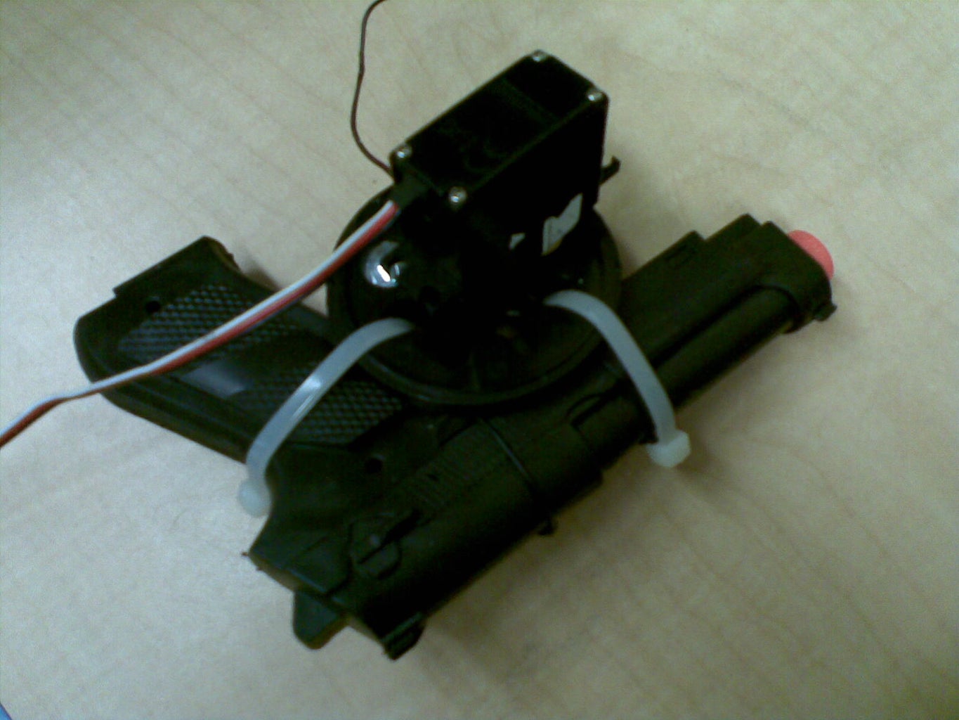


Mount the gun onto a continuous rotation servo[Image 1].
Secure it onto the gun support[Image 2 & 3].
Secure another continuous rotation servo with wheels[Image 4] onto the servo mount[Image 5 & 6].
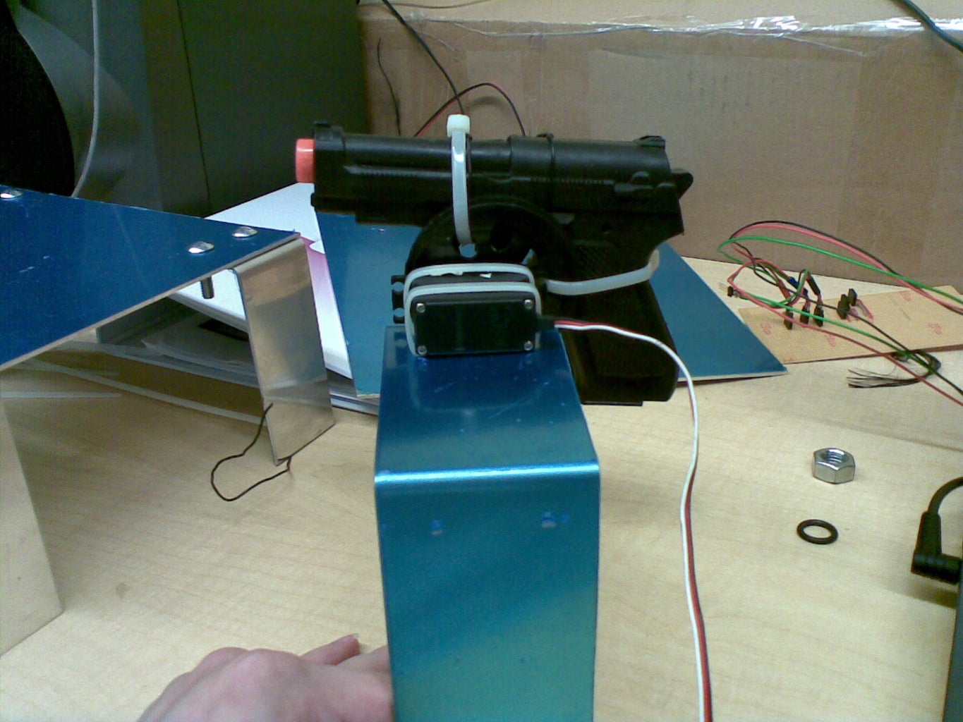
Step 4: Putting Everything Together Part 2


Mount the feet to the base using screw and nuts[Image 1].
Do the same for the gun support and the turning panel.
Then put everything together[Image 2-6].
Step 5: Soldering


Circuit Diagram[Image 1]
LDR: Pin 2, 4, and 7
Servo for trigger: Pin 3
Servo for tilting: Pin 5
Servo for panning: Pin 6
LDR Circuit:[Image 2]
The potentiometer is to calibrate when it detects the laser is blocked off.
Make sure to calibrate the LDR Circuit to the surroundings.
When laser is shine on the LDR, the output should be 5V.
When laser is blocked off, the output should be at 0V.
Step 6: Code
There are alot of values at the top of the code which can be tweak and play around with.
Things needed to be changed based on the servo you're using:
SERVOPANSTOP, SERVOPANMSFOR180, SERVOTILTSTOP, SERVOTILTMSFOR90, SERVOTRIGON, SERVOTRIGOFF
There are also some codes for calibration of LDR Sensors.
Just use the serial monitor on arduino(57600 baud rate) to see the current output the LDR are producing.
Attachments

Step 7: Setting Up for Action!


Make sure the LDR is calibrated and the laser is pointing at it.
Panning:
This video shows the gun turning to the preset angle when my hand block the LDR from sensing the laser.
Gun In Action:
This video shows the gun moved to the preset angle and trigger being pulled when the trip-wire system senses an obstacle.

Participated in the
Arduino Challenge


