

Introduction: Building a Solid State Tesla Coil

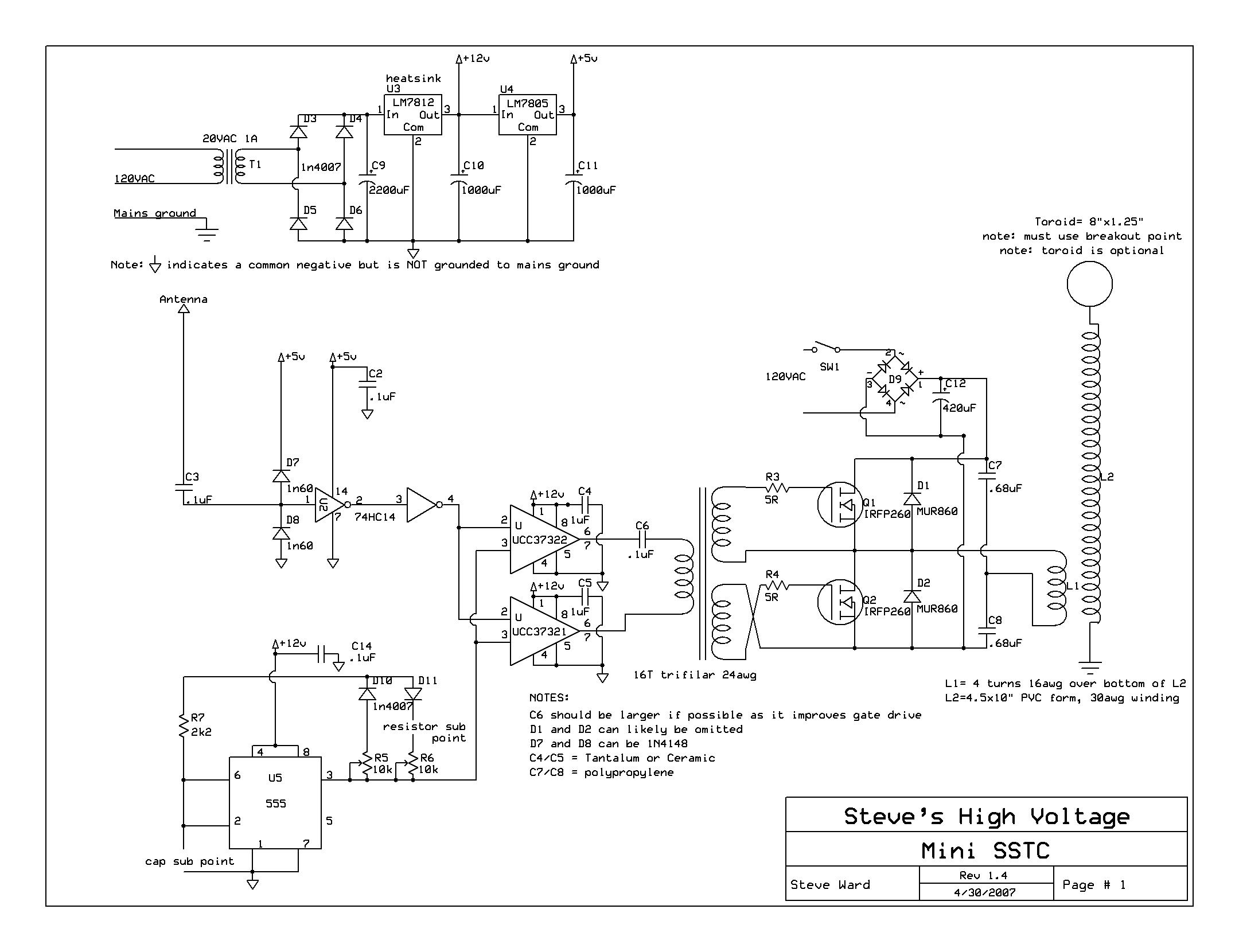
!This instructable is meant to give detailed instructions on building a solid state tesla coil based off of steve ward's mini sstc schematic.
Ok, here's the disclaimer.
*********************************************************
I do not hold any responsibility or your use or misuse of this information, in any way. I am not a trained professional and I cannot protect you from the voltages that are part of this project, and any damage this project may cause, wether it be to animal or material. The user assumes all responsibility for the actions they take.
*********************************************************
Well, now that that's over, lets get on to what a tesla coil actually is.
A tesla coil usually has these key components:
*power source
*Switching circuit
*Resonant Capacitor (only for drsstcs, some vttc,s and regular spark gap type coils)
*Primary coil
*Secondary coil
The tesla coil was invented around 1891 by Nikola Tesla. His original intention for the device was to create a wireless energy distribution system. Unfortunately, his design could not send power at even close to reasonable efficiency, as the power was almost all being wasted on corona and arcing. Today, we coilers take this to an advantage.
But what males the tesla coil truly magnificent is the voltage it produces. A typical spark gap type coil takes (usually) the voltage from your wall socket, and steps it up to a couple thousand volts, where it then goes through the switching circuit, through the primary, and is seen on the secondary side as more that 200,000 volts! But how did tesla do this?
The answer is resonance. A resonant circuit, usually consisting of a capacitor and inductor, is much like a slinky. (stretched out) When you give it a push, it bounces back and forth losing momentum with each pass. However, if you keep hitting it every time it comes back, it will start to move really far back and forth at the same speed. (Or frequency) The frequency at which you hit it is it's resonance.
The secondary coil is like our spring. But how do we get voltage from it? Certainly not by hitting it. No, you have to use an oscillating magnetic field from the primary coil to excite it. A normal spark gap type TC would use a resonant capacitor and a spark gap to produce the oscillation, where as our coil (sstc) will use feedback from the coil itself to drive the primary. (using an antenna.)
~~for more info on how a tesla coil works, head on over to Richie Burnett's site or the wiki.
Step 1: The Overview

Our coil will be a solid state type. The schematic we are using was made by steve ward, and belongs to him. This circuit is a relatively simple circuit as far as tesla coils go, and is a good place to start for a coiler that is new to solid state drive. I will say that you should only attempt this if you are confidant that you can work with mains voltage, as this coil does have direct mains voltage running through part of it.
Unfortunately, I cannot currently put up the steps to wind the secondary coil, but I will put up an intractable as soon as possible. But generally, what you need to do is wind many tight turns of thin magnet wire around a pvc form. Don't make it too tall. A good ratio for height is that the height is about 3 to 5 times the diameter.
Anyway, what you will get out of this coil is approximately 7-8 inch sparks. (Depending on how you set the interrupter) I'll go over this later, but for now, that is what you can expect. Trust me, you'll have fun.
*****EDIT: That mystery symbol appears because instructables cant handle the µ and Ω symbol in pictures. go figure! it works here.
Step 2: Equipment


A tesla coil is a very interesting, and fairly complicated device. Aside from building this coil, There is some special equipment I highly recommend using if you power this little beast up. There are dangers involved in a mains-powered-hundred-thousand-volt-producing machine, as it turns out. :D
We wil be doing a lot of soldering for this coil. And I mean a lot of soldering. I used up about five feet of solder at least! So, with that considered, our first items are a soldering iron and a desoldering iron/desoldering pump/soldering wick of some sort, that is, unless you can solder perfectly. Now, unless you have a fancy super durable soldering iron, It is likely that you will be using a radioshack iron. It has been my experience that the tips on these things, even with the most obsessive cleaning, these tips just get eaten away. So, buy an extra tip. ;) You will also want some flush lead clippers to trim down component leads. In case you don't have a store near you, here are some links:
******************
Soldering iron
Desoldering iron
Extra tip
Lead clippers
******************
Now, As I said before, there is more to the coil than building it. When we test it, we should not just go and jam the plug into the wall socket. The equipment I say you must have before you power this thing up is a variac, or switch of some sort two protect yourself from full mains. What a variac is is basically a variable transformer. It allows you to alter the voltage that flows from the wall socket to your device, much like a gigantic kilowatt volume dial. You can find a good variac for around 80 dollars at a local electronics store, assuming they haven't completely turned ti consumer electronics, but I'd recumbent getting one online from say, Fry's electronics. They have two models. A low power one and a high power one. The low power on was enough for me to use on this project.
********************
Low power variac
High power variac
********************
While this Is all the equipment I would require myself, It is nice to have an oscilloscope for measuring gate drive waveforms and looking at interrupter input. It is also nice to have a variable DC power supply for testing the low voltage electronics, but again, it is not required.
Step 3: Parts in Parts


As you can see from the schematic, there are plenty of parts to this circuit.
So, lets get starter with the
fundamental power components:
******************************
25v 2a transformer
bridge rectifier
lm7805
lm7812
50v 2200 µF capacitor (X2)
25v 1000 µF capacitor
5.6kΩ resistor
2.2kΩ resistor
Blue LED (X2)
******************************
Now, the Interrupter components:
********************************
0.1 µF decoupling capacitor
NE555
10kΩ linear potentiometer (X2)
1n4007 diode (X2)
2.2kΩ resistor
0.1 µF capacitor (This can actually be any value you like, It will simply alter the arc appearance/interrupter speed.)
*********************************
Next, we move on to the antenna section:
***********************************
0.1 µF decoupling capacitor
74hc14 hex inverter
6-8 inch long piece of wire
1n60 diode (X2)
0.1 µF capacitor
***********************************
Now, we move on to the gate drive components:
*********************************
UCC37322
UCC37321
1 µF decoupling capacitor (X2)
0.1 µF capacitor
2 foot long strand of wire (X3)
Ferrite toroid
*********************************
Now, for the scary mains filter:
******************************
Bridge rectifier
200v 680 µF capacitor
******************************
Finally, the muscle of this circuit, the half bride:
*************************************************
IRFP260N mosfet (X2)
200v 0.68 µF capacitor (X 2)
5Ω 2W resistors (X2)
Insulating thermal pads (X2, TO-247 type)**
Heatsink with two matching screws and holes*
Thick non-stranded wire, about five feet
*************************************************
ALMOST FORGOT! don't forget
****************************************
SOLDER
****************************************
These are the necessary components. I used digi-key because they are easy to use.
*I got my heatsink from an old atx power supply. There are full of useful stuff!
**Usually also found in tax power supplies.
I also recommend getting some terminal connectors. They make everything so much easier.
***********************
Terminal connectors
***********************
Step 4: The Voltage Supply


So, the first part of the circuit I chose to solder was the voltage supply. This was primarily because it is connected to every other part of the circuit. Anyway, I first soldered in the terminal for connecting the transformer in, right next to it, the low voltage bridge rectifier. Luckily, they match up!
*A tip for soldering long or high current connections: Lay down a piece of metal wire to the path you want to solder. It makes it much easier to apply.
PARTS:
******************************
25v 2a transformer
Bridge rectifier
LM7805
LM7812
50v 2200 µF capacitor (X2)
25v 1000 µF capacitor
5.6kΩ resistor
2.2kΩ resistor
Blue LED (X2)
******************************
Step 5: The Interupter


Next, we move to the interrupter. This is the part that turns the coil on and off. (we need to limit the onetime so that we don't completely wear out those mosfets. The reason we have chosen to make this part before the rest (After the power supply) is so that we can test it before finalizing any connection to turn on the coil.
PARTS:
********************************
0.1 µF decoupling capacitor
NE555
10kΩ linear potentiometer (X2)
1n4007 diode (X2)
2.2kΩ resistor
0.1 µF capacitor (This can actually be any value you like, It will simply alter the arc appearance/interrupter speed.)
*********************************
Step 6: Antenna Section


Now, we will put together our antenna section. This part of the circuit is designed to capture feedback from the secondary to keep the circuit resonating. Because we use feedback to provide the signal to our halfbridge, the coil is always in tune! No worrying if you have that pesky 555 on the right frequency.
***********************************
0.1 µF decoupling capacitor
74HC14 hex inverter
6-8 inch long piece of wire
1N4148 diode
0.1 µF capacitor
***********************************
Step 7: Gate Drive Section


In this step, we will assemble the part of the circuit that combines and amplifies the interrupter and feedback signals to drive the gate drive transformer. These parts can fail more than others, so it's not a bad idea to instal sockets.
*********************************
UCC37322
UCC37321
1 µF decoupling capacitor (X2)
0.47 µF capacitor
*********************************
Step 8: Gate Drive Transformer


The gate drive transformer does exactly what it's name implies. It takes the signal from the UCC's and sends it to the mosfets, as well as isolating the low voltage side from the high voltage side. To make the transformer, first, take your three pieces of wire, and twist them together. This creates a trifler winding. Next, wind the wire around the ferrite toroid 16 times. (Each time the wire passes through the center is one turn) after that, cut the wire so there is about 2 inches on each side of the transformer. Now, take two ends of wire of the same color, and solder each to one output of the gate drive section.
********************************
2 foot long strand of wire (X3)
Ferrite toroid
********************************
Step 9: Mounting Mosfets to Heatsink


Now, when you switch 120 volts at hundreds of thousands of times per second, It is almost indefinite that you will generate some heat. We use a heatsink to channel that heat away from the mosfets, and into the air. To mount them is simple, but DO NOT FORGET YOUR THERMAL PADS. they keep the mosfet drains from shorting out.
PARTS:
**********************************
Mosfets
Thermal pads
Heatsink and matching screws
**********************************
Step 10: The Half Bridge.


Here is the muscle of this coil, the half bridge. what this is are two mosfets that alternate switching on and off to produce alternating current. They do this at a high voltage, mainly so we can pump power trough the primary. this causes a magnetic field to be formed that excites the secondary coil (resonator) and the resonant rise builds up the high voltage. Once it is high enough, it breaks out into air.
PARTS:
*************************************************
IRFP260N mosfet (X2) mounted to heatsink
200v 0.68 µF capacitor (X 2)
5Ω 2W resistors
*************************************************
Step 11: Primary Coil


The primary coil is where all of that work pays off. The signals are amplified and pushed through here to make the secondary make sparks. To make the primary, first, find a circular object about the diameter of your primary, and wrap your thick wire around it five times, leaving ~6 inches on each end. then, using a twist tie, or you hands (If you don't have an easy method of securing it) Hold it together. Get your secondary coil, and put the primary around the base of the secondary. ****As there will be high voltages present on the secondary, (Hopefully) put some kind of insulator between your primary coil and secondary coil if at all possible. However, if you don't have any, just keep the primary as close as possible to the bottom, possibly using hot glue.**** Once that is done, we can move on to our first test!
Step 12: Setup/test! Yay!!!!


Now, we're ready to set up for the test of our coil, or the "first light!"
1. Attach your transformer of variable dc power supply to the low voltage in, and set to above 15 volts.
2. Attach the two leads of the primary coil to your output terminal near the bridge
3. Grab an ac cord that you wont ever want and strip it open, putting the hot and neutral wires into the AC in terminal.
4. Connect the bottom wire of your secondary to the mains ground, if you do not happen to have a better earth growing connection.
5. Plug in your variac and DC power supply and set the variac to zero volts, turned off.
6. Turn on your DC power supply
7. Plug the ac cord into your variac.
8. Turn on the variac
9. cross your fingers and slowly turn up the voltage. If you did it correctly, you should see arcs coming out of the breakout point!
Good luck! And thank you for reading my first Instructable.
Finalist in the
Epilog Challenge


