

Introduction: Building an Acrylic Classic Macquarium


The idea of an aquarium built to fit in a classic Macintosh case, aka Macquarium, has been around for 20 or more years. I didn't invent the Macquarium, but in the mid and late 90s I built several of them and perfected my own unique style of tank.
If you search the internet, you'll find several different plans for building a Macquarium from glass. I always believed acrylic was a better choice because it let me maximize the amount of water in the tank and the bonded seams are quite strong. My design integrates filtration and lighting and provides outstanding access to the tank for cleaning and maintenance.
The pages that follow will tell and show how I build a Macquairum. It's not the only way to do it, but it's my way and I think it's the best way.
Step 1: Taking the Mac Apart


About those Torx screws... A T-15 Torx screwdriver with a 6" blade is needed to take the screws out of the handle and remove the back. If you don't have one, just get out a drill and drill the heads off the screws. Remember, it's never going to be a computer again.
Note that this tutorial illustrates disassembling a Mac 512 model. The SE and Classic versions were slightly different, but I'm confident you can figure it out.
Pic 1- Pry off the programmer's switch (if present) with a screwdriver. Save the switch, we'll use it later.
Pic 2 - Remove the battery door and the Torx screw behind the door. Again, save this piece.
Pic 3 - Remove the two Torx screws from the bottom of the case. Note the "Hyperdrive" sticker. This was an internal hard drive hack for the early Macs. Very cool, very expensive.
Pic 4 - Remove the two Torx screws located deep in the handle recess.
Pic 5 - Remove the back case. There is a special tool designed to separate the case halves, but lacking that you can usually simply position your hands on opposite corners of the back case and slap it upwards - hard. Several times, if necessary. As a last resort, use putty knives to pry the seam open.
Pic 6 - Remove the AC plug on the analog board. Sometimes this plug will be very difficult to remove (extreme heat welds it in place). In that case just cut the wires. Remember, it's never going to be a computer again.
Pic 7 - Remove the plug from the CRT to the analog board.
Pic 8 - Remove the grounding screw attaching the analog board to the frame.
Pic 9 - Remove the analog cable from the logic board.
Pic 10 - Disconnect the anode from the CRT. Note, if this computer has been turned on in the last few weeks, there could be dangerous voltages in the anode. I recommend using a pair of wire cutters with insulated handles to cut the anode wire. If you're certain the computer hasn't been powered up recently, the cap can be removed by sliding a screwdriver under the rubber cap to loose the wires.
Step 2: Taking the Mac Apart - Part 2


Pic 1 - Remove the screws holding the analog board to the frame. Not pictured - one or sometimes two more screws along the front of the analog board.
Pic 2 - Lift the analog boar out of the frame.
Pic 3 - Pull the brightness knob off the analog board and set it aside. We'll put most of it back on later.
Pic 4 - Remove the floppy cable from the logic board.
Pic 5 - Remove 4 Torx screws, one at each corner of the CRT and lift the CRT from the case.
Pic 6 - Pull the logic board out of the frame.
Pic 7 - Remove 2 Torx screws holding the bottom of the frame to the bezel.
Pic 8 - Remove 3 Torx screws holding the top of the frame and life the frame assembly from the bezel.
Congratulation! You've just field-stripped a Mac. Now comes the hard part...
Step 3: Preparing the Bezel


Cover the Apple logo and any printed lettering on the front of the bezel with masking tape to prevent them being scratched.
Pic 1 - On the inside of the bezel, almost everything that sticks up, out, or down must be cut off and ground smooth.
Pic 2 - The curve of the inside of the bezel opening will have to be minimized later as part of the final fitting of the bezel to the case/tank combo. Leave it alone for now.
Pic 3 - This is the socket for the brightness knob we saved earlier. Leave it be for now.
Pic 4 - Use a cut-off wheel on a Dremel to begin removing the interior structures.
Pic 5 - Go slow. Take off small amounts until you get the feel of the tool.
Pic 6 - I cut the bezel structures in two passes. First, I use a cut-off wheel to remove as much as possible without cutting into the bezel frame.
Pic 7 - This is another illustration of the bezel after the first pass with the Dremel using the cut-off wheel.
Pic 8 - Now I go aroun again with a small barrel stone and grind the structures all the way down.
Pic 9 - This is the bezel after all the bits are removed.
Step 4: Cut Out the Lid


Listen up! This is the most important cut of the whole process because it will be the most visible. GO SLOW - NO SECOND CHANCES!
Pic 1 - Our cut will follow the red line in the picture. Move your thumb first.
Pic 2 - Use a straight edge to darken the manufacturing seam along each side. Draw a line about half way between the vents and the rear edge along the back. Draw a line with the same width down through the handle depression.
Pic 3 - Cut a shallow trench along the line. Push the tool against the direction of rotation, else the cut will fill in with melted plastic as you move along. If you see smoke, you're going too fast. Let the wheel and the cut cool for a few seconds and resume cutting. It will take several passes to cut all the way through. Go slow - go straight.
Pic 4 - Cut along the back.
Pic 5 - I cut straight across the handle and don't try to cut on the line yet. After the lid is removed you can go back and trim the handle hole on the case along the drawn line.
Pic 6 - There are a pair of braces on the inside that served as guides for the analog board. You'll need to cut them from the inside before the top will come off. I use a small round metal cutting bit to get through these bits.
Pic 7 - And off comes the lid!
Step 5: Cut the Handle From the Lid


The handle is best removed in chunks.
Pic 1 - First, cut out the open part of the handle as shown. Don't worry about how these cuts look. It's okay to leave a little bit sticking up from the underside of the handle. We'll smooth it down later.
Pic 2 - Now cut off the 2 screw receivers.
Pic 3 - Next, cut a line across the middle of the screw receivers and across the vents at the front and remove the next chunk of handle.
Pic 4 - Cut down the inside of each side of the remaining chunk.
Pic 5 - Cut across the front.
Pic 6 - Remove the last major piece.
Pic 7 - Now cut under the last 2 bits and remove them.
Pic 8 - The lid now only needs the remaining ridges ground smooth.
Pic 9 - And it's finished. For now.
Step 6: Prepare the Case


Pic 1 - The circled structures should be removed. I use a cut-off wheel to take off most of the plastic and follow up with a barrel stone to grind it flat.
Pic 2 - These parts are more tricky. The raised lip around the battery door whould be removed but be careful not to cut too deep or it will keep the battery door from fitting correctly when you're done. The upper bits need to be ground flat to the vent. Both the upper left and upper right may need small adjustments to fit the tank when it's built.
Pic 3 - All done for now!
Step 7: Cut the Tank Pieces


Pic 1 - You will need 3 pieces of acrylic. The easiest way is to buy them cut to rough size, but either way you'll need (in mm):
1 center piece - 221 x 810
2 leg pieces - 255 x 328
Pic 2 - I use a jigsaw with a blade made for plastics. Go slow. If you get the cut too hot, it'll fill in with melted plastic behind the blade.
Pic 3 - The leg pieces need to be trimmed. Clamp the pieces together and cut both at once. The grid points in this picture outline the cuts that need to be made. With the top-left corner being the 0,0 axis, the dimensions are (in mm):
1 - 0,63
2 - 21,23
3 - 227,0
4 - 255,268
5 - 215,273
6 - 215,328
Pic 4 - Draw the cuts then clamp the pieces down and chop away.
Step 8: Bend the Acrylic


The bends that form the tank are created by heating the acrylic with a propane torch. I use a medium flame and move the flame back and forth across the acrylic at a moderate pace. The goal is to soften the acrylic without actually melting the material. If you see a lick of flame from the acrylic after you move the torch away, you're getting it too hot. If the acrylic gets too hot, it will bubble. This doesn't always ruin the piece, but it is unsightly.
Be sure to blow or wipe bits of plastic and dust from the area to be heated.
After the acrylic is soft enough to bend, you'll have a couple minutes to adjust the angle. This is more than enough time so be careful removing the clamps and positioning the piece. Don't try to adjust the angle after it begins to cool or you risk cracking the acrylic. After the piece is completely cooled there will be enough flex in the bends to allow minor adjustments.
Remove the protective film from both sides and clamp the the acrylic to your bench. I use a piece of aluminum foil folded over the edge to protect the bench from the flame.
Pic 1 - Use a square to draw a straight line across the acrylic 192 mm from one end. This will be the face of the tank. A red or black Sharpie type marker works well for this. Clamp the piece to the bench with the line just over the edge.
Pic 2 - Light the torch and start moving it across the acrylic. Even heating is important! Heat by making a pass across the material then move the torch back and repeat the pass going in the same direction. Don't go left-right-left-right as that will tend to overheat the edges and underheat the middle.
Pic 3 - You can also heat from the underside. The goal is even softening from top/bottom/left/right.
Pic 4 - When the acrylic starts to sag, support it with your hand until it's soft enough to easily make the entire bend.
Pic 5 - Now, allow the acrylic to drop Make sure the bend is at about the same angle on both sides.
Pic 6 - Remove the clamps and stand the sheet on its side on one of the end pieces. Adjust the bend angle.
Pic 7 - Place a piece of scrap acrylic under the far end of the unbent portion of the sheet.
Step 9: Bending the Acrylic - Continuted


Pic 1 - With the acrylic properly positioned on the side piece, make a mark about 10 mm from the bottom.
Pic 2 - Lay the acrylic on the bench with the existing bend hanging over and downward. Use a square to draw a straight line across the acrylic along the mark made in the previous step.
Pic 3 - Clamp the acrylic over a piece of aluminum foil folded over the edge of the bench.
Pic 4 - Heat as before until the piece is soft. Bend at about the angle pictured.
Pic 5 - Stand the center piece on the side piece and adjust the angle so that the bottom of the tank is parallel to the bottom of the leg.
Mark a spot 10 mm from the back edge.
Pic 6 - Using a square, draw a line along the mark made in the previous step. Clamp the acrylic and heat until soft.
Pic 7 - Stand the tank on the leg and adjust the bend.
Pic 8 - Place the other leg on top the tank and line it up.
Pic 9 - When the front of the tank is lined up with the legs, line the back of the tank with the spot indicated. Draw a line on both sides of the tank.
Pic 10 - Put a piece of wide masking tape around both sides of the acrylic. You should be able to see the marks made in the previous step through the tape. Draw a line from one mark to the other.
Cut the excess acrylic along the line.
Step 10: Assemble the Tank


Pic 1 - Put the legs and tank pieces in the case to make sure they fit.
Pic 2 - Remove the protective film from the inside of each leg.
Pic 3 - Use bar clamps to position the front of the tank to the legs on each side. The tank should be flush along the front of the leg pieces.
Pic 4 - Now stand the tank up and place another clamp at the top rear of the tank. Line the back of the tank with the top of the legs.
Pic 5 - Make sure the legs now both stand flat on the bench.
Pic 6 - Carefully lay the tank on its face. Use the applicator to apply the solvent to the seam along each side of the front of the tank.
Continued...
Step 11: Assemble the Tank - Continued


The glue used on the acrylic is actually a solvent and it literally melts the pieces together. Once bonded, there is no way to cleanly separate the pieces. Be careful!
Pic 1 - After glueing each side of the face, move the clamps successively around the tank and glue as you go.
Pic 2 - Gluing the bottom. If the seams are smooth and the bends are square, these glued seams should look like mirrors when done. These seams will not leak and will require no silicone sealant.
Pic 3 - Glue up the back. As you do this, periodically set the tank on it's legs and make sure it is square to the ground and doesn't wobble. A not-square tank isn't going to fit well in the case.
Pic 4 - Remove all the clamps and see if it fits.
Pic 5 - Perfect!
If the tank is square and sized correctly, it will fit snugly at the back. You may need to use some pressure to free it from the case once it's been pushed all the way in.
Step 12: Fit the Bezel to the Tank
Way back in Step 3 I mentioned the bezel might need to be flattened to fit the tank. Put the competed tank in the case and make sure it fits all the way. It should fit all the way to the back of the case. At this time, put the bezel on. If it doesn't fit, some of the inner curve will need to be removed.
I don't have any pictures to illustrate this step, but the parts that need to be removed should be obvious. When the bezel fits to the same tolerance when the tank is in as when it's removed, you are done with this step.
Step 13: Build a Filter


Pic 1 - The filter plate pictured was part of a kit for a 55 gallon aquarium and is much larger than what will fit. You can use any plate that is at least 6x8 inches.
Pic 2 - After the tank is built, measure the space available in the bottom of the tank. The width will always be about 8" but the depth will vary between 4" and 6" depending on where you made your bends.
Pic 3 - Cut the sides from the leftover portion of the plate to use with your filter.
Pic 4 - Use masking tape to hold the side pieces while gluing. I've found that the thickened version of the acrylic cement works very well with the filter plate plastic.
Pic 5 - The finished plate fits in the bottom of the tank with about 1/2" to spare on each side.
Step 14: Bits and Pieces


Pic 1 - About that serial number. The serial number contains a date code. In this example, the "F" means it was produced at the Freemont, CA plant. The "6" indicates 1986 was the production year and the "23" means it was assembled in the 23d week.
Pic 2 - Put some thickened acrylic cement on the brightness knob and stick it back in the hole.
Pic 3 - After the glue sets, use the Dremel to cut away most of the knob.
Pic 4 - Next we will trim down the reset switch.
Pic 5 - Get rid of all the bits that would protrude in the shell.
Pic 6 - And glue it on.
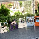
I don't have any better pictures of the light fixture than the picture that opened this Instructable. It's a 110v florescent fixture. You may need to enlarge one of the port holes in the back of the case for the electrical cord to exit.
You can optionally mount the logic board behind the tank as I did in the opening pictures. I cut the ports off the board to minimize its height profile an glued some acrylic blocks to the back of the case to hold the board in place.
Step 15: It's an Aquarium!

If you've made it this far, you now have an aquarium. I hope it's obvious that this is a fairly complicated build. I can only recommend that you practice when you feel the need and don't be afraid to scrap a piece and start again. I certainly did, more than once.
Participated in the
Dead Computer Contest


