

Introduction: Bus Tracking Using BoltIoT
Every day I have to call my friends to know about the status of my college bus.Where is it? When I know that the bus is near to my stop then I will go to my stop.
After learning about the BoltIoT I got an idea that if my mobile app has the option to know where my bus, By that I started doing this project.
Step 1: Components Used :
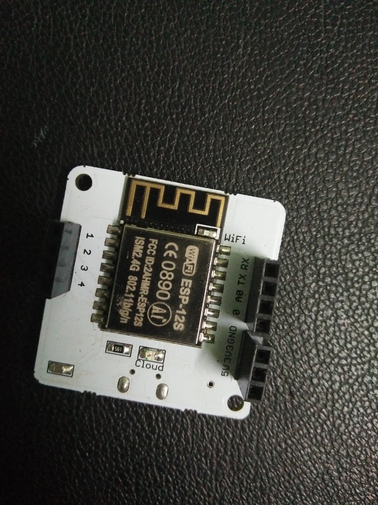


Step 2: Bolt Unit

Bolt unit is an electronic device which has an integrated ESP8266 Wifi chip.It helps to connect to the internet and we can control or get the info from sensors. It works on a 5v power supply.
It can communicate to other microcontrollers using UART communication.
Step 3: Arduino UNO and Battery Cnnection


Here we connect 4v battery in Series and from the +ve wire we will connect to the switch and from the other end of the switch we will connect it to the "+ve" terminal of the Arduino UNO
And from -ve sign of the battery we will directly connect it to the Arduino -ve terminal.
Then we can supply the power using a switch.
Step 4: GPS Receiver

GPS receivers use a constellation of satellites and ground stations to compute position and time almost anywhere on earth.
At any given time, there are at least 24 active satellites orbiting over 12,000 miles above the earth. The positions of the satellites are constructed in a way that the sky above your location will always contain at most 12 satellites. The primary purpose of the 12 visible satellites is to transmit information back to earth over radio frequency (ranging from 1.1 to 1.5 GHz). With this information and some math, a ground-based receiver or GPS module can calculate its position and time.
Step 5: Connecting GPS to Arduino UNO


We will connect the Arduino and GPS using jumper wires
the receiver has 6 pins we will connect
GPS receiver - Arduino UNO
1)GND pin - GND
2)RX pin - 2 pin
3)TX pin - 3 pin
4)3.3v - 3.3v pin
Step 6: Programming Arduino UNO
From the GPS receiver, we will get all the GPS info in NMEA sentence.We will receive up to 19 sentences from the receiver but we need only 2 sentences because they are sufficient for Tracking and knowing the position.
They are $GPGGA, $GPRMC
$GPGGA - Global Positioning System Fix Data
$GPRMC - Recommended minimum specific GPS/Transit dataTO know more about NMEA sentence CLICK HEREFor that we will program arduino to take only this 2 sentances and the reciver will communicate with 9600 baud rate.Add the below zip file in the arduino ide softwareAfter that open INO file and uplode it to arduino using arduino ide software.

Step 7: Connecting Arduino Uno With Bolt Device


BOLT UNIT - Arduino UNO
1)5v pin - 5v
2)GND - GND pin
3) TX pin - 0 pin
4) RX pin - 1 pin
Bolt Starting Serial communication with Arduino UNO
using the link
http://cloud.boltiot.com/remote/YourapiKey/serialBegin?baud=9600&deviceName=BOLTxxxxxx
YourapiKey ---- give your device API key, You can get it from "Developer Console"
deviceName = give your device name, You can get it from "BOLTIOT app" in Google store or app store
keep baud rate to 9600.
Step 8: Creating App for Tracking


Go to MIT app inventor WEBSITE
Then sign in with your Google account.
Then "START NEW PROJECT "
give name and drag and drop the components in screen 1
You can see the components in the image and we can change their properties
after go to "blocks" and connect the blocks as shown in the above image.
In BUTTON1 block give the URL "http://cloud.boltiot.com/remote/YourapiKey/serialRead?till=10&deviceName=BOLTxxxxxx
YourapiKey ---- give your device API key, You can get it from "Developer Console"
deviceName = give your device name, You can get it from "BOLTIOT app" in Google store or app store.
In SCREEN1 block give the URL "https://rl.se/gprmc"

Participated in the
Invention Challenge 2017


