

Introduction: Camera Panorama Robot Head (panograph)


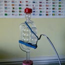
Ever wanted to take pictures of a panoramic scene at the press of a single button? This instructable will teach you how to build a robotic head to mount your camera on, which in turn mounts on a tripod. The robotic head will move in two axes to enable the camera to be panned left and right as well as up and down
There are a few pre-requisites:
I've used a Canon camera which is loaded with CHDK alternative firmware. *check comment on this later on. Visit http://chdk.wikia.com/wiki/CHDK to check your camera compatability.
A little soldering is involved as well as some practical mechanical skills
This is released under Creative CommonsAttribution-Share alike 3.0 license http://creativecommons.org/licenses/by-sa/3.0/
Step 1: Build Steps

Here I've added an index which I hope will make things easier for you.
1 Upper Rig assembly
2 Gear bearing assembly
3 Servo PCB wiring & fixing
3 Picaxe programming
4 Final assembly
5 Load CHDK on your camera
6 Calibration
7 Example panoramas shot in location in North Wales
Step 2: Shopping List

1x Brookes basic tilt frame for KAP http://www.kapshop.com/product_info.php?cPath=6_26_42&products_id=159 9 pounds 50p
1x Brookes better gear guide http://www.kapshop.com/product_info.php?cPath=6_26_42&products_id=75 8 pounds
camera bush screw http://www.kapshop.com/product_info.php?products_id=231 2 pond
2X servo motors http://www.mutr.co.uk/product_info.php?cPath=13_530&products_id=1009437 3 pounds each (You'll need an extra one if your not firing the shutter with CHDK)
1x picaxe servo board (AXE024) http://194.201.138.187/epages/Store.storefront/?ObjectPath=/Shops/Store.TechSupplies/Products/AXE024 7 pounds 50p
2x Gear sets http://194.201.138.187/epages/Store.storefront/?ObjectPath=/Shops/Store.TechSupplies/Products/GWC031 one pound each
22mm aluminium cylinder cut to 50mm length (can be much shorter depending on your tripod head clearence) http://cgi.ebay.co.uk/ALUMINIUM-ROUND-BAR-ROD-5-8-DIA-x-250mm-Long_W0QQitemZ270282531024QQcmdZViewItemQQptZUK_BOI_Metalworking_Milling_Welding_Metalworking_Supplies_ET?hash=item3eee1820d0&_trksid=p4634.c0.m14.l1262&_trkparms=|301:0|293:1|294:30
1 four cell AA battery holder + PP3 battery clip
various nuts, bots & split washers
tie clips
1x toggle switch
for noise supression
4x clip on ferrite noise supressors
4x 100nF ceramic capacitors
tools
dremmel type drill with attachments
1/4-20 tap for attaching rig to tripod
M4 tap for attaching rig to tripod mount cylinder
soldering iron
multimeter
Cable for programming the picaxe http://194.201.138.187/epages/Store.storefront/?ObjectPath=/Shops/Store.TechSupplies/Categories/SoftwareCables/CablesAdapters 3 pound (you will need a serial to usb adapter also if your pc does not have a serial port
vertical drill stand, or access to a workshop to drill holes in aluminium rod ready for tapping
Step 3: 1 Upper Rig Build Pt 1


Upper Rig build Pt 1 : Mount Stepper motor to the rig
Attach a stepper motor to the outside cradle of the rig using 2 4mm diam. nuts and bolts.
Step 4: 1 Upper Rig Build Pt 2


"Upper Rig build Pt 2: Drill holes where needed in the rig"
Drill a 5mm hole centrally as shown on the outside cradle base. The pivot screw will pass through this hole.
Drill a 5.8mm (just slightly bigger than 1/4 used for camera holder screw)" hole centrally along the longest length of the inside cradle of the rig but the depth position will depend on the camera you are using. Measure the base of your camera from the centre of the tripod bush hole to the back of your camera, add a couple of mm & you've got the measurement from the back of the inside cradle
Step 5: 1 Upper Rig Build Pt 3


"Assemble rig parts"
Attach a 4mm diam. threaded rod to the left hand side of the outer cradle as shown in the picture. ( I used a long nut & cut the head off)
Position the rod into the inner cradle using one of the pre-drilled holes so that the distance between the rod centre and the inner cradle base is about 20cm. Use one of self tapping screws that came with your servo accessory kit to screw the other arm of the inner cradle to the servo arm centre hole. Check before screwing that the iner cradle base runs parallel to the outer cradle base.
Step 6: 2 Gear Bearing Assembly

1 First assemble a 4.5mm diameter, 28mm thread length bolt and a 32mm gear. I added a little super glue to make sure these parts were locked together.
2 Washers were added for spacing so that the shaft gear aligns with the servo gear. Now thread the bolt along with gear & washers through the gear assembly piece.
3 next add the 60mm bearing
4 add a washer and small split ring who's diameter is smaller than the outside rim of the bearing assembly
5 Loosely hand tighten a nut
6 Add a split washer
Drill a hole in the centre of one end of the aluminium cylinder . Tap this hole with a 1/4" 20 tap (drill size matches the tap). Marry the reverse end of the cylinder to the gear assembly piece as shown in the picture. Locate two predrilled holes in the assembly & mark through to the cylinder end. Drill and tap these two holes (I used an M4 tap). Next locate the screws and tighten.
Finally Mount the round servo attachment onto the servo shaft. Attach a servo motor to the gear assist assembly . Screw the gear shown in orange here onto the round servo attachment using small self tapping screws.
Step 7: 3 Servo PCB Wiring & Fixing Pt 1

"Prepare the Servo motor picaxe controller PCB"
Noise generated by the servo's has been identified as a problem that affects picaxe timing. This can be minimised by adding suppression capacitors across the power lines of the pcb. So, solder 100nF capacitors across the power supply to the picaxe (on the reverse, solder side of the pcb)
Also, solder the other capacitors across the power lines of the servos. Refer to the attached pic & be careful not to create any short circuits here.
Step 8: 3 Servo PCB Wiring & Fixing Pt 2

"Solder the USB cable to the servo controller pcb"
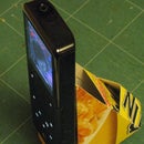
If your using CHDK to trigger the shutter on your camera automatically, you'll need to cut a standard USB to mini USB cable to approx 25 cm in length (from the mini usb connector which is the end you'll use). Strip a small length of the outer sleeve, exposing the inner wires. Trim all but the red and black wires & strip the ends of these to copper
The red & black wires need to be soldered to two pins of the servo connectors as shown in the picture.
IT IS VERY IMPORTANT TO GET THE POLARITY RIGHT AS THERE IS A POTENTIAL TO BREAK YOUR CAMERA IF YOU GET THEM THE WRONG WAY ROUND. DO THIS AT YOUR OWN RISK.
Another important thing to check is the voltage for your particular canon camera used for remote triggering. I'm using a Canon G9 which seems fine on the 5V that the servo board provides. Check http://chdk.wikia.com/wiki/CameraFeatures for the trigger voltage for your camera model. Also I urge you to check this voltage and polarity before connecting your camera with a multimeter.
nb As an alternative to remote shuttering using the camera's mini usb connector, you can mount a servo on the shutter post provided with the rig. I've not tested this method but should work fine.
Step 9: 4 Final Assembly Steps

Attach assembled gear bearing & upper rig
The gear assembly and upper rig are attached by the shaft screw. This is located in the hole you drilled in the centre of the base of the outer cradle of the rig. Screw a nut to secure. The next step will take a little trial & error and is easier in practise than to describe.
You'll need two spanners for this. Tighten the two nuts to fix to the outer cradle firmly. Adjust the position of the lower of the two nuts so that not too much force is applied to the bearing (servo then cannot move). Conversely, if too slack the camera assembly will wobble.
Attach two pcb mounting posts on the outside cradle of the upper rig & mount the servo controller pcb, holes are already pre drilled for you.
Attach the 6V battery holder comlete with AA rechargable cells using tie clips as shown.
Step 10: 5 Programming the Picaxe

A overview of picaxe can be found at http://www.rev-ed.co.uk/picaxe/
Basically download the programming editor found at this link and connect up the serial cable (if no serial socket on your pc use a serial to usb convertor)
Copy & paste the code below to programme your picaxe:
nb the latest code is version 0.2, take the appropriate code for your canon firmware sdm or chk
'*** Panograph by Waldy 0.2 for sdm
'*** Program constants
symbol top = 175
symbol bottom =250
symbol left = 180
symbol right = 100
symbol vstep = 25
symbol hstep = 20
symbol servo_delay = 1000
symbol camera_steady_delay = 2000
symbol camera_ready_delay = 2000
main:
GOSUB Init
for b2 = top to bottom step vstep
for b1 = right to left step hstep
servo 1,b1
pause servo_delay
GOSUB take_picture
pause camera_ready_delay
next b1
servo 2,b2
pause servo_delay
next b2
end
take_picture:
high 4
pause 30
low 4
return
Init:
servo 2,top
pause servo_delay
SERVO 1,right
pause servo_delay
low 4
return
'*** Panograph 0.2 by Waldy for chdk
'*** Program constants
symbol top = 175
symbol bottom =250
symbol left = 180
symbol right = 100
symbol vstep = 25
symbol hstep = 20
symbol servo_delay = 2000
symbol camera_steady_delay = 4000
symbol camera_ready_delay = 2000
main:
GOSUB Init
for b2 = top to bottom step vstep
for b1 = right to left step hstep
servo 1,b1
pause servo_delay
GOSUB take_picture
pause camera_ready_delay
next b1
servo 2,b2
pause servo_delay
next b2
end
take_picture:
low 4
pause 30
high 4
pause 1000
low 4
pause 1000
high 4
return
Init:
servo 2,top
pause servo_delay
SERVO 1,right
pause servo_delay
high 4
'GOSUB take_picture 'dummy pic
return
*****Panograph controller v0.1 for sdm
** Program constants
' Delay to slow down servo motion (30ms default)
symbol servo_delay = 60 'recommended delay between servo movements
symbol top = 160 'max y position
symbol bottom =220 'min y position
symbol left = 180 'min x position
symbol right = 100 'max x position
symbol vstep = 20 'vertical increments
symbol hstep = 20 'horizontal increments
symbol pic_delay = 100
symbol camera_steady_delay = 4000 'delay to steady camera after movement
main:
GOSUB Init
for b2 = top to bottom step vstep
for b1 = right to left step hstep
servo 1,b1
pause servo_delay
GOSUB take_picture
pause camera_steady_delay
next b1
servo 2,b2
pause servo_delay
next b2
end
take_picture:
high 4
pause 30
low 4
return
Init:
servo 2,top
low 4
return
Step 11: 5 Load CHDK on Your Camera

Check http://chdk.wikia.com/wiki/CHDK_in_Brief for a summary of CHDK.
Currently only a variant of CHDK called SDM works with the rig. This can be downloaded from
http://stereo.jpn.org/eng/sdm/index.htm
"notes"
Copy SDM to your camera's SD card.
You'll need to make your SD card bootable.
Enable remote shooting from SDM menu
Step 12: 6 Calibration

Although I haven't done this accurately, the results are quite favourable. Servo rotation is limited to about 180 deg rotation. This is important in terms of horizontal rotation as the servo wire will physically limit the rig servo rotation if not carefully positioned. With the rig assembled, check the horizontal extreme position of the the rig by manually rotating the upper rig. If the servo cable snags, manually adjust the rig position with respect to the bearing assembly so the cable doesn't snag at full travel.
With 4 vertical moves, I adjusted the other servo/ rig arm position by trial and error so that the camera line of sight is symmetrical wrt the horizon
Step 13: Results and Further Development


"Results"
I've posted a handful of panorama's created by this rig on a very recent holiday in north wales. I was more in the business of enjoying my holiday than experimenting with the rig. However, hope you enjoy the results http://www.wizfamily.co.uk/album/panorama
nb you'll need a HDView addon to view these images. If using firefox, download the addon, close firefox, run the downloaded file before restarting firefox.
Here the rig was set to take 5 pictures in the horizontal & 4 in the vertical. If the rig code was set to step much finer & the camera is set to a greater zoom setting, the result will be much finer (more detailed)
"Further Development"
Probably the most pressing is to do more work to eliminate the electrical noise generated by the servo motors as previously mentioned. I tried to introduce a 'camera steady' pause after each move step, which did not work out.
I've suggested on CHDK forum for the SDM firmware directly interact with the rig eg set panorama extreme positions. (At the moment this is fixed in code) Keep your eyes peeled.
Improve/ replace gear bearing mechanism.


