

Introduction: Canon Remote Shutter for R/C


This instructable details how to remotely take a photo/video with a Canon camera using an Arduino, a remote control transmitter and receiver.
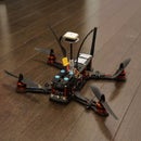
I have a quadcopter running arducopter 2.8.something. At the time of writing this instructable, remote shutter is not enabled. I read somewhere that they’re working on it for 2.9.
I can’t wait that long. A friend of mine (a research fellow at Monash University School of Geosciences) needs to take detailed photos of coastal rock platforms, and I already said I have the capabilities to do so, but I didn’t. Now I do.
Step 1: Equipment/Materials.


- A Canon camera. Any camera, but it must be a Canon, so we can hack it with CHDK
- Mini USB male connector. I cut the end of the chord for my old mp3 player.
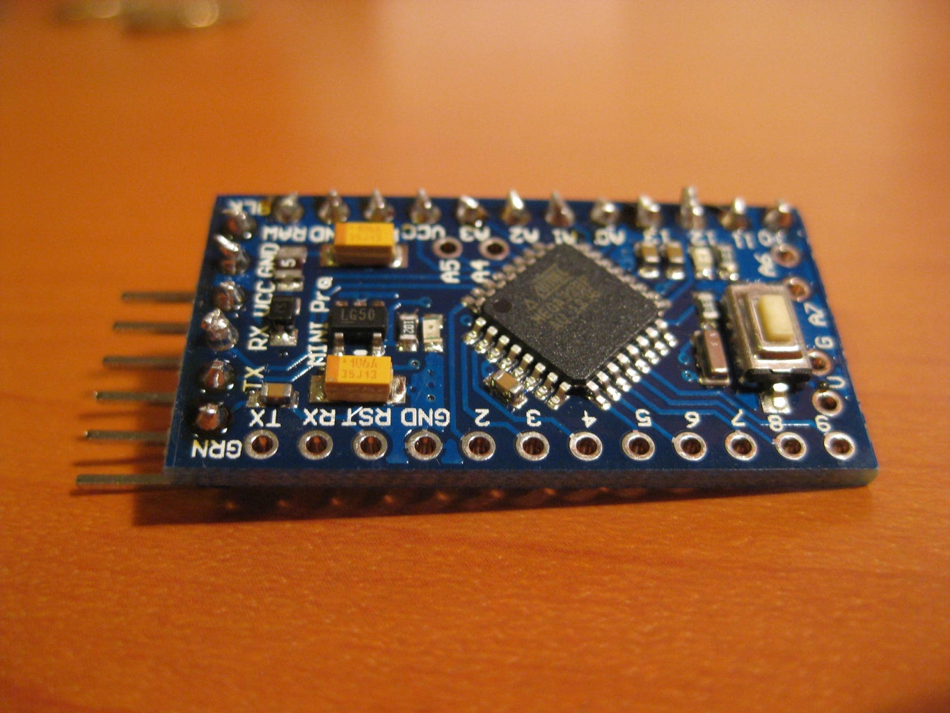
- Arduino. I used a Pro Mini because I need it to be as light as possible, but any Arduino will do.
- Insulated electrical wire. I used pieces that have the female headers on them so they easily connect to the R/C receiver pins.
- Heat shrink
- Soldering iron + solder
- R/C Tx + Rx. I have an 8 channel Flysky 9x pair, but any set with a spare channel will work.
Step 2: Hack Your Canon With CHDK

It is outrageously easy to install CHDK.
****edit****
waterwingz commented that there is an even easier method, which you can read here
http://zenoshrdlu.com/stick/stick.html
************
Download ACID from here to determine which CHDK build to download.
http://www.zenoshrdlu.com/acid/acid.html
Take a photo with your camera and drag the photo into the specified box. ACID will determine what kind of camera you have from the photo metadata and the greyed out download buttons will come to life.
Click 'download stable CHDK'
Once the CHDK is downloaded, get SMDinst from here
http://www.zenoshrdlu.com/clickpansdm/sdminst.html
Browse for your 'Stable CHDK' folder and select it in the SMDinst app, select 'Copy all files from' in the appropriate drop-down menu, and click prepare card. For older cameras (earlier than about 2010) you may have to tick the 'make FAT16 bootable. I did.
***********WARNING************* "Prepare Card" will format the SD card, erasing everything on it. This must be done to install CHDK, so make sure there's nothing important on it.
If that goes through, then you have successfully set up CHDK. This loads every time your camera turns on if the SD card is in. It does not modify you camera permanently, and the moment you delete it from the SD card, your camera will be back to normal. Why would you though?
Lock the SD card by moving the little tab on the side, and put it in your camera. You have to lock it for CHDK to load up, but it still records onto the SD card, even though it's locked. It takes about 5 seconds after you turn the camera on, for CHDK to load.
- Enter the alt menu. This is a special settings menu which sets the functions enabled by CHDK. For my Ixus 80 you press the print/share button, then the menu button.
- Navigate to ‘Miscellaneous Stuff’ at the very bottom.
- Choose ‘Remote Parameters ‘ at the very bottom of this new section
- Select ‘Enable Remote’
- ‘Switch Type’ = OnePush
- ‘Control Type’ = Normal
Leave the rest of the settings and press menu to save and exit.
Step 3: Shutter Trigger Cable.
Now to make the cable for the Arduino to trigger the camera.
The diagrams attached are taken from the CHDK wiki at
http://chdk.wikia.com/wiki/USB_Remote
Cut the USB cable to a suitable length and strip the end. You only need the red and black wires. You can cut the other two away. These colours are the USB standard, and it seems that even cheap cables follow this convention.
Solder a black header wire onto the end of the black USB wire, and a WHITE header wire onto the red USB wire. You don’t have to use these colours, obviously (electrical current flows regardless of the wire colour, I have discovered) but this follows standard hobbyist R/C convention of white being ‘signal’ rather than using red ‘power in’.
Heat shrink it neatly and put your new cable away for safe keeping.
Step 4: Flash This Sketch to the Arduino.
//Arduino Pro Mini w/ ATmega 328P Canon remote shutter controller
// by Patrick Leschinski
//patrick.lski@gmail.com
void setup()
{
pinMode (13, OUTPUT);
pinMode (A0, INPUT);
Serial.begin(9600);
}
void loop()
{
int pwm = pulseIn(A0, HIGH, 1000000);
if(pwm>1500)
{
digitalWrite(13,HIGH);
}
else
{
digitalWrite(13,LOW);
}
Serial.println(pwm);
}
//----------------------------------------end sketch----------------------------------------------------------------------------------------------------------
EDIT:
I fixed a typo in the code on the 14th July, which stopped the Rx signal from being read.
To flash the Arduino Pro mini, which doesn’t have a USB port, I used my Arduino Uno. I pried the ATmega out of its socket, and connected the following Uno pins to the Pro Mini pins.
(Uno -> Pro Mini)
Tx -> Tx
Rx -> Rx
5v -> Vcc
Reset -> GRN
GND -> GND
Then plug the Uno in via USB, select ‘Pro Mini 16 GHz 328P’ as the board to be flashed, and hit it!
Step 5: Set Up Your Tx

If you have a FlySky 9x or Turnigy 9x, you can follow these steps.
- Go to the settings panel
- Select Aux-CH
- Set Channel 8 to ‘Gear’
- Go to ‘Display’ to check which way the Gear switch needs to be for on and off. Reverse if needed. The bar all the way to the right will simulate a press of the shutter button, and all the way to the right simulates releasing the shutter button.
Step 6: Plug Everything In


- Connect Ground of the Rx to a ground pin on the Arduino
- Connect a 5v out of the Rx to Vcc on the Arduino
- Connect Ch 8 signal out of the Rx to pin A0 of the Arduino. Do not confuse this with pin 0 - it is pin A0. In this situation there is no need for the ADC capabilities of pin A0 so you could use a regular digital pin, but A0 is specified in the given sketch, so you have to use it.
- Plug the white wire from the camera cable in pin 13 of the Arduino. I used pin 13 because now the onboard LED lights up whenever a shutter button press is simulated.
- Plug the black camera cable wire into a ground pin on the Arduino. If there isn’t one spare, or it is more convenient, you can plug it into a ground pin on the Rx.
Step 7: Take Pictures!

When everything is powered up, flick the Gear switch to focus your camera, and flick it off again to trigger the shutter. Flick up to focus again, and off to trigger the shutter.
I'm quite proud of my pictures

Runner Up in the
Drones Contest


