

Introduction: Capacitive Sensing for Dummies
For someone new to electronics, capacitive sensing can be really confusing. Even for someone who's been exploring capacitive sensing for a week, it's STILL really confusing. Luckily, you'll have this this handy guide to help you on your road to becoming a capacitive sensei. Here you'll find a bunch of guides, tips, tutorials and general information about this unstable and strange sensor technology.
Step 1: The Boring Stuff

Before we move on to the fun (but mostly frustrating) projects you can embark on with capacitive sensing, let's take a quick look at how it really works.
How does it work?
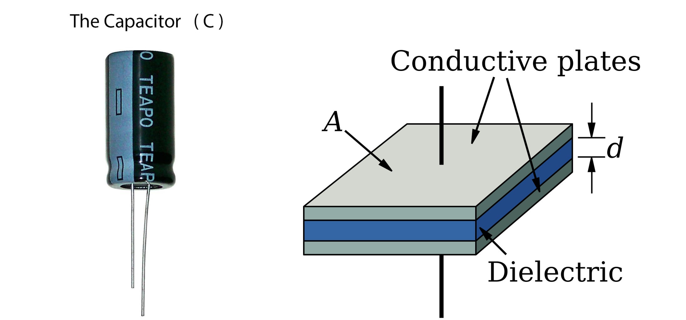
To understand how capacative sensors work, first you have to understand how a capacitor works.
A capacitor consists of 2 electrical conductive surfaces (also called electrodes), one is connected to the positive pole of the electrical circuit and the other is grounded. Between these surfaces there is a non-conductive layer wich is called a dielectric. The capacitor can be compared to a small battery. When sending a pulse to the capacitor, it quickly charges. When the signal goes to zero, the capacitor discharges. This creates a delay in the pulse due to the time it takes to charge and discharge the capacitor.
A capacative sensor works in the same way as a capacitor. The sensor itself is only a conductive surface and will start working as a capacitor by the proximity of any other conductive surface, for example by skin (as long as it has a relative negative charge).
When making a capacative sensor with Arduino you will have an output that transmits a pulse, and an input which receives the pulse and compares it to the transmitted pulse. When you you put your finger on or near the sensor it creates a delay in the pulse, and this delay is recalculated by the CapSense library and generates a value you can use for triggering etc.
Step 2: Stuff That Uses Capacitive Sensors


Step 3: Making Your First Capacitive Sensor

You could go off and buy a ready-made capacitive sensor from Adafruit or Sparkfun, but where's the challenge in that? Capacitive sensors are easy to make yourself with an Arduino board and some basic electronic components.
You will need:
1 x Arduino board. We used an Arduino Uno.
1 x Arduino USB cable.
1 x Breadboard. Not really necessary, but makes things a bit easier.
1 x Metal object, like a paperclip, copper plate or a piece of aluminium foil. This will be the connecter with which you interact with to send a signal to your Arduino.
Electric wires
A resistor. We have found that you should use at least 1 MOhm, but tried using up to 37,6 MOhm. The higher the resistance, the higher readings you will get. If you don't have big enough resistors, you can daisy-chain a bunch of them together.
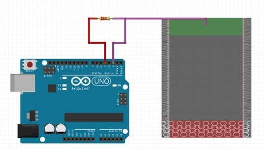
Step 1: Download the CapSense library from Arduino. Extract the files to Documents/Arduino/libraries. Restart Arduino.
Step 2: Connect your resistor to the breadboard. Connect a wire from one side of the resistor to pin 4 on your Arduino board. Connect the other side of the resistor to pin 2. Connect that same side of the resistor (The one that goes to pin 2) to a long wire, ending in the metal object of your choice. See the images for a more visual explanation.
Step 3: Open up a new Arduino sketch and paste in the following code:
#include <CapacitiveSensor.h>
CapacitiveSensor cs_4_2 = CapacitiveSensor(4,2); // 10 megohm resistor between pins 4 & 2, pin 2 is sensor pin, add wire, foil
void setup(){
cs_4_2.set_CS_AutocaL_Millis(0xFFFFFFFF); // turn off autocalibrate on channel 1 - just as an example Serial.begin(9600);
}
void loop(){
long start = millis();
long total1 = cs_4_2.capacitiveSensor(30);
Serial.print(millis() - start); // check on performance in milliseconds
Serial.print("\t"); // tab character for debug window spacing
Serial.println(total1); // print sensor output 1
delay(10); // arbitrary delay to limit data to serial port
}
Step 4: Compile and upload your sketch to the Arduino. Open up the serial monitor. The first number is the time (in milliseconds) the board uses to process the calculations. The second number is the reading you're getting from the cap sensor.
And presto! It's done. Not the most exciting result, I know. But every great journey starts with a single step.
Step 4: Design Tips
Now that you're ready to use capacitive sensors in your own projects, there are a few things you should consider when designing your projects:
1. Do you really, REALLY need a capacitive sensor?
Meaning, is there any other sensor that can also do the job? If you need to sense proximity, a light sensor might work. If you want to measure pressure, a pressure sensor could do the trick. Capacitive sensors are wildly unstable, and require constant calibration, unless they are in a perfectly controlled environment. They're great for situations where you want to avoid any mechanical stress on a switch, as the user doesn't ever need to really be touching the sensor itself. Meaning, you can go all Scandinavian on your projects and make wooden switches, for instance. Or invisible ones. Another great advantage is the the sensor will only be activated by human touch, which could go a long way in making sure that electronics don't activate on their own in your suitcase.
2. Grounding is everything.
During testing (Which you can see in the video at the end of the 'ible) we found out that even taking your shoes off while activating a cap sensor will have a huge impact on the signal strength. If the Arduino is powered by a computer, plugging the computer to a wall socket might double or even triple the signal strength. Increased negative charge equals increased signal strength.
3. Cover up your sensors.
Not just because it looks cool, but also because it helps to stabilise your signal. You don't need more than a piece of clear cellotape, but you could take it so far as to fully enclose the sensor in a solid material, such as ABS plastic.
4. Use smoothing in your code.
If you followed the tutorial in step 3, you'll notice that the signal from a cap sensor can be highly erratic. Therefore it's a good idea to use some kind of smoothing function in your code. We used this one and it did a great job in stabilising the signal.
5. Control as much of the environment as possible.
Everything from air humidity to electromagnetic noise to someone touching a cable will affect the signal strength. Eliminate as many variables as you can. Using shielded cables and making sure no other electronic equipment is operating in the immediate vicinity are two easy precautions you can take. Solid grounding will also reduce interference.
6. Bigger surfaces = bigger signals.
The bigger the surface area of your sensor, the stronger your signal will be. A big surface area is also better for triggering the sensor at a distance.
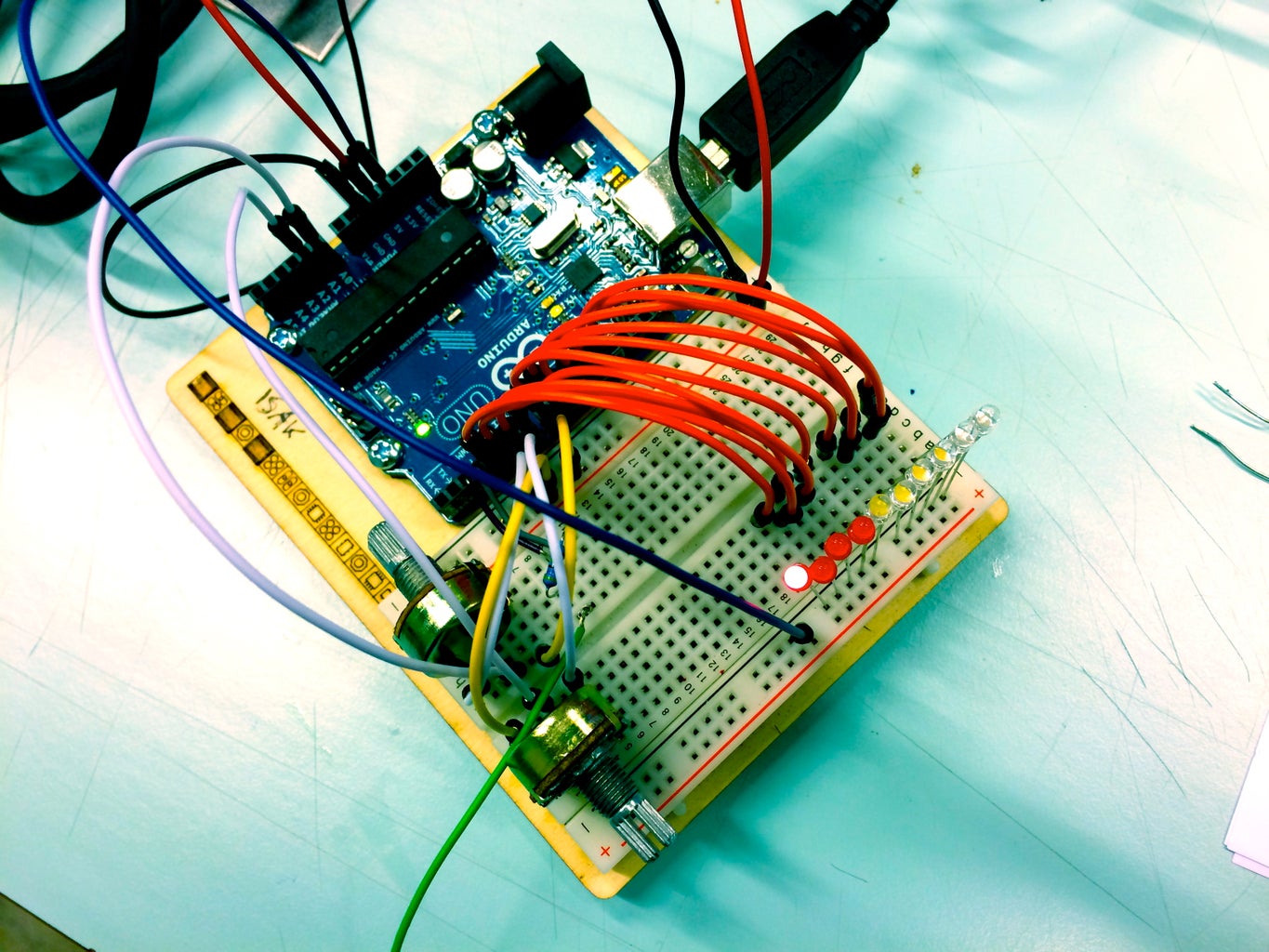
Step 5: Cap Sensor Diagnostics Tool


Because there are so many variables that determine how strong the signal is, we decided it would be a good idea to have some sort of tool that would give us the ability to determine how suited a sensor would be at a glance. What we came up with is an Arduino device that can be hooked up to any surface with an LED bar graph that will light up according to how strong the signal received from the surface is. Since the reading from one surface might be tenfold that of another surface, we also included two sensitivity knobs. One for the minimum reading, and one for the maximum. Through testing we found that you really only need the maximum reading knob, so feel free to exclude the lower threshold knob. We did not use any resistors for our LEDs, and after using the device for a couple of days, it's still working fine, but there's no telling if and when they'll stop working. If you choose to use resistors, it's probably a good idea to hook them up to 5V instead of 3.3V.
You will need:
1 x Arduino board. We used an Arduino Uno.
10 x LEDs. We used one red, seven whites and two blues, but use whatever you want/have.
2 x Potentiometers. You can exclude one if you want, as the usefulness of a knob to control the lower threshold of the device is questionable.
7 x 4,7 MOhm resistors. That's what we used, but you can use a different amount if you want. The more resistors you have, the greater the resistance range you can explore. The lower values they have, the higher the resolution of the resistance range.
Electric cables
Breadboards (Optional)
Step 1: Wire up everything as shown in the fritzing diagram.
Step 2: Open up a new Arduino sketch and paste in the code below. The code uses a smoothing function for a more stable output. We used this code to get the LED bar graph lighting up correctly, making only slight modifications.
#include
const int ledCount = 10; // the number of LEDs in the bar graph
const long numReadings = 10;
int sensorPin1 = 0;
int sensorPin2 = A1;
long readings[numReadings];
long index = 0;
long total = 0;
long average = 0;
int ledPins[] = { 4, 5, 6, 7,8,9,10,11,12,13 }; // an array of pin numbers to which LEDs are attached
CapacitiveSensor cs_3_2 = CapacitiveSensor(3,2);
void setup() {
// loop over the pin array and set them all to output:
cs_3_2.set_CS_AutocaL_Millis(0xFFFFFFFF);
Serial.begin(9600);
for (int thisReading = 0; thisReading < numReadings; thisReading++) readings[thisReading] = 0;
for (int thisLed = 0; thisLed < ledCount; thisLed++) { pinMode(ledPins[thisLed], OUTPUT); } pinMode(sensorPin1,INPUT); pinMode(sensorPin2,INPUT);
}
void loop() {
int bottom;
int top;
bottom = analogRead(sensorPin1);
top = analogRead(sensorPin2);
int bottommap;
int topmap;
bottommap = map(bottom,0,1023,0,3000);
topmap = map(top,0,1023,100,30000);
long start = millis();
long total1 = cs_3_2.capacitiveSensor(30);
total= total - readings[index];
readings[index] = total1;
total= total + readings[index];
index = index + 1;
if (index >= numReadings)
index = 0;
average = total / numReadings;
Serial.print(millis() - start);
Serial.print("\t");
Serial.print(bottom); Serial.print("\t");
Serial.print(top);
Serial.print("\t");
Serial.println(average);
delay(10);
int sensorReading = average;
int ledLevel = map(sensorReading, bottommap, topmap, 0, ledCount);
for (int thisLed = 0; thisLed < ledCount; thisLed++) {
if (thisLed < ledLevel) {
digitalWrite(ledPins[thisLed], LOW); }
else { digitalWrite(ledPins[thisLed], HIGH); } }
}
Step 3: You're done! Compile and upload the sketch to the Arduino and you should be able to get a more graphical output of the signal strength. Add or remove resistors to increase or decrease the signal strength. More resistors means more strength. We mounted a series of resistors on a separate breadboard so that we could change the resistance faster. Turn the potentiometer connected to A1 to increase or decrease sensitivity.
Step 6: Experimentation Video
Step 7: Resources
What follows is a list of useful resources for those exploring capacitive sensing.
Serves as a good introduction to the technology, but also gets into the more techy side of things, if that's what floats your boat.
A good place to start for those wanting to build their own cap sensors.
Designer's guide to rapid prototyping of capacitive sensors on any surface
A good guide focused on buttons for consumer electronics, with tons of useful charts and diagrams.
How to Select the Right Touch Sensing Approach for Your Design
Design tips for using cap sensors
Touche for Arduino: Advanced touch sensing
Tutorial for mimicking Disney's Touché with an Arduino.
YouTube: Capacitive sensor, Theory, application and design
Video explanation of cap sensing
Sparkfun's guide for using a capacitive touch breakout board with an Arduino
Instructable tutorial for making a lo-fi piano using cap sensing


