

Introduction: Chimera: $60 DLP High-Res 3D Printer


I have been on a hunt for the past several years to find a cheap and simple, yet moderately high resolution 3D printer. I had 3 different 3D printers partially constructed when I heard about the amazing technology of DLP Stereo lithography (SLA) printers. I have finally found enough parts at the right price to construct a fully functional printer capable of amazing quality with spending less than $100. Top down DLP printers in their simplest form have only one axis of motion, a video projector, and minimal electronics. They do not require a heated or perfectly level bed, there is never a clogged or wrong temperature in the extruder as it does not use an extruder. And the resin used has a comparable price to FDM printers.
I Started this project to show that you don't need a lot of money or special equipment to start experimenting with 3D Printing. While this printer was not meant to give the same quality as an expensive printer such as the form 1, the results I got exceeded my expectations. There are still a few bugs to work out but, it definitely is usable. If you would like to see a video of it printing, the video is in Step 12.
The chimera (ky-meer-a) is a mythological creature that is made up of 3 different animals, this printer is made using the recycled/modified parts of 3 different categories (projector, toys, and old computer stuff), hence the name.
I am always looking for constructive criticism, let me know of any ways I can improve on the project, or the instructable!
Before continuing I would like to apologize for the not-up-to-current-standards pictures and video quality, I am working with almost or over a decade old equipment in bad lighting. I will try to update the photos once I get a better quality camera and/or find a better location for pictures.
Update 7/14/15 This project won one of the enthusiast grand prizes in the 2015 3D printing contest. Thank you everyone for their votes, and thank you instructables for continuing to be the best online DIY community! I am glad I could contribute to this site and hope my next project will spark as much interest as this one did.
Step 1: What Is a Dlp Printer?
Let’s start out with the basics, in 1986 Charles W. Hull created stereo-lithography as a form of fabrication that uses ultraviolet light to cure a polymer resin to create solid objects. Since then, projection technology has opened up a highly accurate, fairly cheap, and easily accessible form of ultraviolet emission. A DLP printer is different from the "normal" FDM (fused deposition molding) 3d printers that have been dominating the community, an FDM machine uses an extrusion system similar to an advanced hot glue gun that is attached to an apparatus that can move the extruder in an X, Y, and Z direction. The extruder must follow a path made by a computer to print objects. A DLP printer uses the stationary projector to display the entire X and Y portions at once onto a resin that turn from a solid into a liquid from the light emitted by the projector in the shape of the projected image, and uses one axis for the Z motion.
Top Down vs. bottom up
- Resin tank vs. resin vat - The biggest difference in the abilities of top down vs. bottom up printing comes from the limits of the container that holds the resin. In a top down system the platform and object slowly gets submerged deeper into the resin and is limited by how deep the tank is. This is not a problem if you only want to make small detailed prints as I designed this printer to do. Bottom up printers use a shallow tank and the object rises up out of the resin and is not limited by the vat size.
- Viscosity - Top down system require a low viscosity resin in order to work properly, as it relies on the resin to flow on its own over the platform, and level properly when the object is lifted to skim just below the surface. Without a wiper apparatus you have to wait for resin to settle before you are able to print with your desired layer thickness. Luckily, MakerJuice's SubG+ has a low viscosity and works very well for top down systems. Bottom up printers squish the resin to the desired layer thickness.
- Warping - Warping effects both types of printers, but effects each printer differently. In a bottom up printer, each layer of the object is created pressed between the bottom of the vat and the previous layers, that combined with the ability to use low viscosity liquids provides very little warping per layer. However with top down systems the object is free to curl and warp if it does not stick properly to the build platform. And low viscosity resins tend to have a slightly higher shrinkage per volume unit.
- Object stress - Bottom up printed objects suffer from numerous forces acting on it throughout the build process. Every layer has a suction force trying to pull the object off of the build platform, and tilt/slide mechanisms are applying forces in many directions at once, along with gravity pulling down on the entire object. In a top down printer, the printed object has almost the same density as the liquid resin so gravity it not a problem. And the only forces acting upon the object is shrinkage.
- The ultimate advantage to top down over bottom up is its simplicity, where bottom up printers require tilt/slide mechanisms and expensive/messy vat coatings, top down printers only move up and down and can use almost any container for the tank.
Even though bottom up printers are capable of printing larger and higher quality objects with less resin, I decided to build a Top down printer for its simplicity and ease of construction.
Step 2: Gather Parts
Edison once said "invention requires imagination and a pile of junk." I had a few ideas, so it was time to head to the pile of junk (really, I have one). Out of that pile came old printer carriages, steel smooth rod, old disk drives, stepper motors and other misc electronics. The one part that I had to buy was the DLP projector.
Parts.
- 1x mitsubishi XD221u 1024x768 video projector -> ebay $50, was $40 when I bought mine.
- 1x computer disc drive laser deck assembly (must be one with a stepper motor) ->Free, from scrap disc drive
- 1x Arduino UNO/Duemilanove , or atmega328 based Arduino clone- $4 ebay
- 1x Easydriver v4.4 ->$2 ebay
- misc wire, solder, etc.
- (optional) Ability to etch circuit boards (you can protoboard/breadboard it if you have to)
- (possibly) 5v, .5A power supply. Some laser decks can be powered by the USB port by the Arduino, some may need a power supply to be plugged into the Arduino or M+ on the easydriver to make the motor move. It will depend on the power of your USB port. My deck did not need one.
Total=$55.5
(optional for frame) scrap wood->free or 2x4ft MDF board ->$10 home depot
While the actual 3d printer can be built for less than $60 you will still need resin to print anything.
MakerJuice red G+ resin -> 500ml for $35 or 1L for $60
I only spent $39.99 for the projector, and got the resin for "free" using gift cards acquired from bing rewards. And I already had all of the other parts. So I built this for a total cost of only $39.99, which is very good especially considering the quality of the parts that it prints.
Step 3: Choosing a Projector

There are many projectors out in to market today, and as this is the most important part of the 3d printer, it is important to choose a good one. There are a few projectors i see referenced as being used for 3d printers, namely the the dell 2300 and 2400, and the infocus 2104. But in theory any DLP projector can work as long as you keep a few thing in mind when choosing a projector.
Projector types
- DLP
You need a projector that uses DLP(Digital Light Processing) technology for projection. DLP technology uses an array of micro mirrors to turn pixels on and off. The mirrors reflect the light directly from the bulb to the emitter lens without passing through much.
-LCD
What you don't want is an LCD(Liquid Crystal Display) type of projector. LCD projector direct the light through an LCD panel that uses transistors to turn pixels on and off, if the pixel in on, then the light has to pass through several layers of plastic, glass, and polarizing filters before the image gets projected. Much of the UV light that is needed to cure the resin gets absorbed by the LCD panel and there will not be enough left over to cure the resin. once again, LCD projectors can NOT be used for resin based 3d printing (that i know of)
Resolution
Resolution (or res for short) is the number of pixels that the image is projected at. The native resolution of the projector is very important as it will determine the quality of the printed object. Common resolutions for projectors are 800x600, 1024x768, 1280x800, 1280x1024, and 1600x1200. Obviously the higher the resolution, the better the quality of the printed objects will be, but high-res projectors are not cheap. i would recommend not going any lower than 1024x768, which is the most common, but it is possible to go with lower res projectors, just don't expect great results.
NOTE: there is a difference between supported and native resolutions. supported resolutions is the max resolution of the video feed that is given to the projector. Native resolution is what the actual projected image will be displayed at. be careful of advertising "scam" that will make it sound like an amazing 1080p (1920x1080) quality projector, but the quality is actually terrible and usually around 400x320. This is something that usually happens with Chinese no-name projectors, but it is still important to be aware of the difference.
Lumens
This is how bright your projector will display the image at. The higher the lumen rating the projector has, the faster it will be able to cure then resin. I don't know what the minimum rating is, but the xd221u projector is rated for 2300 lumens and it takes longer than i would like for each layer at 10 seconds exposure time.
Step 4: Modify the Projector


While the XD221u will not cure the resin without modifications, the focus distance is too far and the curing time is too long at 15 seconds exposure per layer. The focus had to be modified for close distances and the UV filter had to be removed allow more UV light through. Making it cure the resin faster is easy, just remove the filter (glass square) on the front of the bulb. Making the projector focus at ≈7" was a bit more difficult. The service manual has been attached for assistance in dis-assembly if you are using an xd221u projector, but the modification should be similar for most projectors.
WARNING: I am not responsible for any damage, injury, blindness, death, etc. that may be inflicted upon you during these instructions. Your actions are your own and you should know what is and isn't safe to do. Use common sense and you will be fine.
Now for the fun part. The steps correspond roughly to in order of the pictures
Modifying the focus
1-3. Remove the bulb cover and bulb from the projector. There are two screws and two clips holing the bulb in.
4. Remove the 8 screws from the bottom of the projector
5-6. Remove the three screws holing the back plate on, and use a flat head screwdriver to remove the back plate.
7-9. Lift the top of the projector off being careful not to rip the ribbon cable connected to the top buttons. Lift the clip holding the cable to the motherboard and slide the cable free.
10-12. Remove the zoom adjustment piece by prying out the 2 clips holding it in. Then remove the zoom frame by screwing the two screws holding it in place.
(WARNING: for the next several steps do not touch any of the lenses or you will not be able to get a clear picture after you are done.)
13-14. Remove the four screws holding the focus lens assembly in place, there is very little room for a normal screwdriver here, I had to use pliers and a Philips piece from a multi-head screwdriver. To remove and replace these.
15. Turn the assembly upside down and rotate the focus lens outward until its stops, inspect the circumference of the body of the focus assembly and you should see a very small screw that is screwed into the focus lens housing and is colliding with the outer assembly case. This is the screw that prevents the lens from unscrewing too far.
Remove this screw. You will now be able to turn the lens farther to focus at a closer distance. (WARNING: removing this screw allows the focus lens to be unscrewed all the way and fall out of the projector if turned too far, be aware of this as you focus the projector)
16. Re-assemble the projector but don't put the bulb in yet. Reverse the steps used to disassemble. The lens can now turn far enough to focus at close distances, which is needed for high resolution prints.
16-18. For the xd221u, there is a tab on the focus lens that will prevent the lens from turning to far, this is both good news and bad news. the good news is that I can use this to prevent the lens from falling out if it gets turned too far, the bad news is that the lens still can't turn far enough to focus at the distance I was looking for. To fix this use a file and slowly file down the tab until there is 1-2mm of distance from the tab to the projectors case.
I found that the lens will fall out when turned to around 300° (looking head on with 0° at the right) so I super-glued a scrap piece of scrap plastic to the case about 5mm from the point the lens will fall out to stop the lens from turning too far. This gives me a focus distance of approximately 6.75 inches from the front of the projector and a projection area of 4in wide by 3in tall.
Modifying the bulb - Then I needed to remove the UV filter to make the layers cure quicker.
19. If you are at the right angle you can see the square piece of glass at the front of the bulb that is the UV filter.
20. Remove the screw holding the metal plate on.
21-22. Use a small flat head to pry the metal clips out and up.
23. Remove the UV filter by lifting the glass out or by tilting the bulb until it falls out into your hand.
24. keep the UV filter in a safe and protected place, if you ever want to use the projector to watch movies or play games on, you will need to put the filter back in.
Put the bulb back in to projector, and turn it on. If everything works, well done! if not, open it up make sure that the ribbon cable for the buttons is attached correctly, no other cables were disconnected, and that the circuit board didn't suffer any damage. Connect a video source. Turn the focus as far as it will go without falling out, use a piece of paper or the wall to measure a rough estimate of the focal distance, this will be fine-tuned after it is attached to the printer.
Attachments

Step 5: Z Axis


The Z axis is the second most important part of the printer. It must be able to move smoothly without any wobble or twisting. I was considering constructing one, but that would require a significant amount of measuring, cutting, drilling, having to work with linear bearings, attachment plates, bells and pulleys, or lead screws, backlash, and all the other stuff associated with linear motion, or i could settle for a smaller but easily acquired, free, pre-built, and extremely fine precision assembly that has everything needed in one package.
As many people have found, a laser deck assembly from a computer disc drive is perfect for this purpose. the one i used is one that i have had around for a while, waiting for a good use for it. I do not know what model drive it came out of, but any assembly will work as long as it uses a stepper motor (4 wires) and not a DC motor (2 wires). As a rule of thumb the newer the disc drive, the more likely that it will be the correct type of motor, I've taken at least 50 apart over the years and i would estimate 90% of the DVD burners i have taken apart contained the correct motor while only 50% off DVD players and only 10% of CD players had the correct motor.
These pictures are for reference of how to take a drive apart and what you want from the drive. while i did not use this particular assembly it does fit the requirements and could be used. I would like to thank groover and his excellent pocket laser engraver instructable for bringing disc drive laser decks to my attention as viable candidates for linear motion.
Dissemble the Disc drive
- Use a paper clip to eject the disc tray.
- Push in the clips on either side of the tray to remove the faceplate.
- Remove the screws holding the bottom plate on.
- Remove any cables connected to the circuit board and remove any clips or screws holding the circuit board in place.
- Lift the circuit board away and remove the ribbon cable connected to the laser assembly.
- Flip the drive over and lift off the metal cover
- Remove the screws holding the deck assembly in place.
- Lift up and slide the assembly out, some drives have the rubber pieces secured in the plastic, remove them from the plastic frame without damaging them. You want to keep all four rubber pieces with the laser deck.
- If you want, remove any unnecessary parts such as the spindle motor.
Once you have taken the deck out of the disc drive, solder four 6inch wires and a four pin female header to the stepper motor. This will be used to connect to the shield that will be made later.
Attachments
Step 6: Build Platform


The only requirement for the build platform is that it is made from a material that your print will stick to without peeling itself up, yet will not force you to pry the object off and potentially damage the print in the process. The material I see used most often is aluminum. I had a piece of 1mm thick aluminum sheet that was part of the back light housing for an LCD monitor. After measuring the resin vat dimensions I scratched the design into the sheet and cut it with tin snips. Then bent the cut out at a 90° angle to form the build platform and the suspension beam. I had to bend the beam in the middle move the platform farther away from the z axis to fit properly in the resin tank. When cutting the sheet metal I made the platform 4mm smaller than the resin tank which gave 2mm clearance on each side to allow the resin to move freely from below the platform to above the platform without any pressure building up.
Step 7: Resin Tank

The resin tank for top down printers are fairly simple. Almost any container can be used as long as you follow a few guidelines.
The container must be
- Waterproof with no leakage
- Slightly larger than your desired build size
- and not dissolve as the resin is a very strong solvent.
I looked at my options and decided on the top from an acrylic container that i had lying around, it is roughly 50x50x35mmind is sufficient for the prototyping stage. I recently found a glass container at goodwill for $.50 that is 3" diameter and 3 inches deep which should work perfectly for my needs.
Step 8: Frame


This machine was built with two frames, one to hold the z axis, platform and resin tank, which I am calling the Zframe. The other frame simply holds the projector above the zframe, and allows the zframe to move up and down to allow the projector to focus on different resin tanks.
Z axis, platform, and resin tank
I like to design as I go along, so I turned to the most versatile prototyping material in existence, LEGOs. Yes these are technically a toy, but i have not found any other materials that allow you to quickly construct, make small changes, or tear down a bad idea as easily as LEGOs do. The requirements for the zframe were...
- Must be able to mount the z axis (disc drive laser deck)
- Must hold the resin tank securely below the z axis and build platform without allowing any motion
- Must be able to rest on whatever main frame that will be constructed later
The z axis mounting problem is something that I had solved a while ago for a different purpose, but it worked well for the Chimera. As pointed out earlier, LEGO technic bushings fit very well into the rubber/plastic mounting holes that already exist in the laser deck, so all that was needed to mount the laser deck was four Lego axles protruding from a wall in the right locations.
The vertical spacing is easily adjusted by how many layers of full bricks and flat bricks are used. But most laser decks will not fit the standard spacing of technic beam holes. This issue was solves by mounting LEGO axles within the wall that allow a Tpin to slide for any spacing.
something to be aware of is that when any resin touches the LEGOs it has a similar effect that gallium has on aluminum(video), essentially it will make the LEGOs disintegrate. So if you don't mind if some LEGOs get destroyed then go ahead and use LEGOs, it didn't bother me as these were actually megablocks ;). otherwise you can make the frame out of wood, which I am planning to do once I decide on the final size vat I am going to use.
Main frame
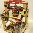
For the main from the only requirements were that it held the projector up and had a space for the zframe below the projection area. While LEGOs could be used, I've found that interlocking bricks are not good for large and stable structures. So I turned to the other "toy" that can make large, lightweight, and sturdy structures, yet has a similar flexibility for alterations to the design as Legos do, and that is K'nex.
Several years ago i was heavily involved with the k'nex community here on instructables, making everything from the Foldable knex gun to the 5 foot cannon and in doing so i discovered the amazing strength and versatility of K'nex, and have amassed over 100lbs of it. it is an excellent tool for learning the physics behind large structures, and how to make large structures that can withstand a significant amount of forces acting upon them.
K'nex made constructing the frame easy, its simply a base, two towers and an adjustable platform to accommodate for different size resin tanks until I find a suitably permanent one.
Wood frame
As promised I have designed a frame that can be completely out of wood for anyone who does not have Legos or K'nex. I made this one out of a 11.5"x28"x.5" particle board shelf that I pulled out of the trash with a circular saw and a drill press. Home depot has a 24"x48"x.5" MDF for $10 that is more than enough wood and will work better than the particleboard I used. The SolidWorks CAD files are at the end of the step, I will make blueprint files from the SolidWorks files soon. I will also make printable PDF documents that can be used as stencils if for those who like to use those.

Step 9: Electronics


One of the best features of a top down system is the simplicity of the electronics. Instead of the expensive Arduino MEGA and RAMPs shield that many DIY 3D printers use to control the many features, the cheap Arduino UNO can be used because there is only one axis to control and maybe a shutter (optional). I etched a shield for the Arduino, which I designed in Cadsoft EAGLE. But if that is not something you are able to do, fear not! the schematic is simple and can easily be made on a breadboard. If you want to put a little more work into it, you can program an ATMega328p chip with the firmware and etch a all-in-one board whose design is included in the files attached.
Shield Connections
- Easydriver - This is Where the Stepper motor controller goes. The Easydriver was chosen because the motors in the disc drive operate off of 5 volts which Easydrivers can operate at. the smaller and more popular "stepstick" drivers require at least 8.2 volts before they even turn on, which will cause the small steppers to overheat.
- Zmotor - This is where you plug in the bi-polar stepper motor from the disc drive deck assembly.
- Top and bottom limits - (optional) These are optional, i have not configured GRBL to use limits yet, but they are available if you want to use them.
- Iris - (experimental) connects to a solenoid that opens and closes a mechanical iris, more in the future updates step.
- Power terminals - (Optional) This gives you the option to connect a non-wall wart power supply.
The Shield has 1/8th microstepping enabled for high resolution movement.
Attachments
Step 10: Arudino Firmware


I tried several different firmwares for the Arduino UNO before deciding to use GRBL 0.9i. In my experience, GRBL is the best option for print quality, compatibility, ease of use, and customization. To get your arduino setup for the printer you will need to upload the GRBL firmware, and configure GRBL to your machines specs. Download the attached zip file and extract it to the desktop. Connector your arduino to the computer.
Uploading the firmware
GRBL firmware is in .hex format, and the arduino software does not allow you to upload .hex file to the arduino, so we will be using a different program called xloader.
- Open the extracted files, open the xloader folder, and open xloader.exe
- Click the browse button navigate to the extracted files on oped the "
grbl_v0_9i_atmega328p_16mhz_115200_for_SO2.hex" file.
- In the "device" box chose "Uno(ATmega328)"
- Select the correct COM port
- Make sure the baud rate is set at 115200
- Click "upload"
- Once the message "28690s byte uploaded" appears you are ready to go to the next step
Configuring GRBL
- For this step, open up a serial terminal, for this I will use GRBL controller.
- Select the correct com port.
- If needed, change the baud rate to 115200.
- Open the serial terminal in the top right corner
- Several lines of code should appear, at the top it should say "Grbl 0.9i ['$' for help]"
- The only thing you need to change is the "steps per mm" for the z axis. In the top command bar type "$102=53.333" , this will set the number of steps per mm your Z axis moves at. 53.333 is the number of steps per mm for the "normal" type of lead screw, the one I used had 157steps per mm which I found by trial and error
You are now able to use the Arduino for controlling your printer.
Attachments
Step 11: Software


Out of the many open source software options that I looked at, only Creation Workshop by envision labs seemed to provide the compatibility and customization options that I required. I have included the zip file that contained the software and settings I used pre-setup, but it may require some tweaking for your own machine. Start by extracting the zip file to the desktop or other location. Open up CreationWorkshop.exe and follow the instructions.
Configure the machine
- Profile selection - Click the plus button to create a new profile and name it chimera (or whatever you want)
- Build Size - Take a rough measurement of the x and y dimensions of your projected area. note that this is NOT the dimension of your build platform, these are the dimensions of the total projection area, measure as best you can, but its doesn't need to be exact. This will be adjusted after the first test print.
- Com port - plug in the Arduino, click configure, and chose the com port that your computer assigned to the Arduino, and make sure that the baud rate is set at 115200.
- Machine controls - this is where you tell the software what features you printer has, as this one only has a z axis, check the corresponding box.
- Displays - connect your projector to your computer, most laptops will have a video-out connection, the xd221 projector and my laptop both have VGA connections so that is what i used. if your computer does not have the options for duel monitors, it should let you use the main monitor, but it will make the process more difficult. click the second display then the plus button to use the second monitor (projector) as the display used for printing.
- Configured displays - shows the display that will be used for the printing process.
- Apply changes - make sure that you click this to save any changes you have made before moving on.
Configure the Slicing Profile
Profile selection - Click the plus button to create a new profile and name it chimera (or whatever you want)
- settings -
- Slice thickness - this is how thin each layer of the print will be, set the layer height to .1mm, this is a good place to start.
- Exposure time - this is how long each layer will be projected onto the resin, the longer the time the harder each layer will be, but each layer will also shrink more. 10 seconds (10,000 milliseconds) is what everything pictured was printed at, but i think that it may be slightly overexposing the resin. This is something you must test and adjust as each printer/projector will be different.
- Bottom exposure - for the very first few layers you want to be sure that your print is anchored sufficiently to the build platform these lawyer are exposed for a longer period of time to ensure proper adhesion. I doubled the layer time for 20 seconds (20,000 milliseconds).
- #bottom layers - this is how many of the first layer will be exposed for the longer duration. again this will be slightly different for each printer, but i am having success with using the first three layers.
- Enable anti-aliasing - Checking this box can help if straight lines are being printed with jagged edges, but it shouldn't be a problem.
3. Lift and sequence -
- Z lift distance - This is how far down the z axis will go to allow resin to flow over the top of the previous layers. for larger prints or higher viscosity resins you will need to increase this distance, but for the small prints that i am doing 3mm is fine.
- z speeds - you don't want to move the print to fast, or the forces of the resin flowing could collapse some of the finer details or thin walls in your print. 75mm per second is slower than it needs to be, but i feels its better safe than sorry.
4. Auto Calc - this will calculate the estimated time that it will take for the printer to complete the lift sequence, this is important as it is the time for which the software waits before projecting the next layer.
5. Build Direction - VERY IMPORTANT - make sure that you have top_down selected as the printer type. your printer will not work if the wrong type is selected.
6. Apply changes - make sure that you click this to save any changes you have made before moving on.
I would highly recommend using a second computer to run your software on, while you can use your computer at the same time you are printing, there are many things that could go wrong if you are doing other activities such as browsing the Internet (instructables addiction? guilty.) or playing games.
1. Pop-ups - these can cause MAJOR print failures. remember that the projector is connected as second computer monitor, so any popup can appear on the second monitor resulting the the projector displaying a totally white screen and hardening the entire top layer of the resin, which will ruin your print without hope of recovery, be very difficult to remove, and is a waste of material.
2. Slow/freezing issues - if the computer runs slow or hangs up due to an excessive load on the processor or graphics card, creation workshop can freeze mid-command or even skip commands, with will result in a failed print.
In order to avoid these problems its recommended that you do not touch the computer while you are printing an object.
Attachments
Step 12: Calibrating/printing Process


In order to get the best quality prints you will have to calibrate the machine. This involves making sure that the projector is at the optimal focal distance from the build platform, and that the X and Y dimensions or correct. Make sure the machine is plugged in and turned on before starting.
Focusing the projector
- Connect the projector and make sure that it is set as the second monitor for the computer.
- Open the attached grid calibration file and move it over to the second monitor so that the grid is projected down onto the build platform.
- Turn the focus lens as far as it can go without falling out, you should be able to see a grid on the build platform. WARNING: Be careful what angle you are viewing the projection, the light from the projector is VERY bright and may cause damage to your eye if reflected off of the build platform at the right angle. You should be fine viewing between 0-30° from the platform, the worst angle is looking almost directly down onto the platform.
- On the K'nex frame, I built the zframe platform to slide up and down for easy adjustment. Whatever way the frame was built, the distance between the build platform and the projector needs to be changed to get the best focus that can be observed.
- Once you think you have a good focal distance, open up CreationWorkshop and click on the go to the "control" tab. Use the buttons to slowly move the platform up and down observing the "fuzziness" of the grid lines until you find the "sweet spot". Mark this location as this is the place you will start your prints at.
- NOTE: If the platform is moving in the opposite direction of the command, disconnect and unplug the Arduino from the computer. Unplug the motor, rotate the connector 180° so instead of it plugged in 1-2-3-4 it will be 4-3-2-1. Reconnect the Arduino and try the controls again, they should be going in the right direction.
- You can now close the grid calibration picture.
Calibrating the prints
Congratulations! It is now time to actually see what this printer can do, but before making anything detailed, the X and Y dimensions need to be calibrated.
Load the calibration cube
- Use the control tab in CreationWorkshop to move your platform to the focus height that you found earlier, and make sure that the platform can move at least 15mm down from that location.
- Click on the "3D View" tab. in the top left corner click on the folder to open a file. Open the 10mm calibration included in this step.
- Click the slice button at the top (the piece of cake)
- In the pop up, select the slicing profile that you setup (chimera in my case), and click "slice"
- Once it is done slicing click on the "slice View" tab you should see a black screen with a white box in it.
- In the bottom left corner click on the "view slice on device display" button. This will display the current layer on your projector.
- Check the location of the object, it will likely not be centered on your build platform. This is ok.
- Go back to the 3D view tab and open the move panel on the right move the object using the + and - buttons an estimated distance and click the slice button again.
- Once that is done repeat steps 5-8 until the projected object is centered on the build platform make a mental note of the location of the object on the 3D view area, this is the location that you will need to place any object you will make in the future.
Printing process
- Fill the tank up with resin until the top of the resin is level with the top of the build platform.
- Use the control tab to move the platform 10mm down, then 10mm up. This will give the build platform a thin coat of resin for the first layer.
- Click the "play" button to start the print. The print will take 20-30 minutes to complete (28min with my settings)
- NOTE: for the calibration cube, try to keep track of which side of the cube is the x axis and which side is the y axis as you go through the rest of the process.
- Once the print is done you have two option depending on how the build platform is secured. 1. If the platform is removable, then remove the platform and either pour isopropyl alcohol (IPA or rubbing alcohol) over the print to wash off any uncured resin. or 2. while it’s not recommended, If your build platform is difficult to remove or permanently in place then use a razor blade or sharp thin knife to remove the print from the build platform, don't touch it with your fingers as it is not good to get the uncured resin on your skin. The print will be very slippery so put on vinyl glove and wrap the thumb and pointer finger in paper towels, which will allow you to grip the slippery object. Then rinse the object with isopropyl alcohol.
- Do not soak your print in IPA or your prints will turn white and cause problems.
- Lightly dab off the prints and let it dry for a few minutes.
Post Curing
Once the print has dried you usually need to perform some sort of post-cuing process to fully harden the resin. There are several options for this.
- The easiest way is to simply leave it out in the sunlight for 10-60 minutes depending on the brightness of the sun, and the size of the object. This however is very difficult to regulate and get a perfect cure. And some people report that the sun causes the prints to turn a yellowish color (think old newspaper after its been in the sun too long)
- A better option is to use a UV source such as a UV light bulb or UV LEDs for the exposure, this will be much easier to control the curing time and intensity.
- What I do. I have a 5mW 405nm UV laser pointer that I go "scan" the parts with, this is not the easiest option but its working until I build a UV light box, which is the best option.
- As previously stated, the absolute best option is a UV light box. Aptly named as a UV light box is a box with reflective internal coating (aluminum foil) and a source of UV light (usually LEDS) that creates a very even exposure and precise control over the timing.
Calibrating the X and Y axis.
Now that you have your calibration cube printed it likely that it’s not exactly square or the wrong size, this is normal and easily fixed.
- Use a caliper to measure the x and y dimensions of the cube, you could try to use a ruler, but you will not get sufficiently accurate measurement. My cube measures Y=9.94mm and X=9mm, this is not the requested 10mmx10mm so we have to tweak the settings.
- Go back to "configure machine" in creation workshop.
- Click "adjust" in the build size settings.
- Under "model size", change the 2 to 10 for both X size and Y size. Change the "measured size" dimensions to whatever your corresponding measurements were.
- Click OK
- The program has now adjusted your x and y build dimensions.
- Go through the process of printing, curing, and measuring again. Your cube should now be much closer to the desired 10mm. (mine was 10.05x10.02) which was good enough for me.
- If your new measurements are not close enough, or you are OCD and need absolute perfection, then you can go through the calibration process again with the new measurements.
Your done! Go enjoy your new printer! If you made one I would really like to see it and the results. If you have any questions, concerns, or comments, let me know! I will respond as soon as I can. If you liked my instructable please vote for it in the 3D printing contest, while this machine can do very fine details and is an amazing printer, it still cannot do the large scale or structure parts that a FDM Printer can do, and I have So many ideas that require the abilities of a FDM 3D printer. Thanks for looking and I hope you enjoyed this instructable!
Attachments

Step 13: Results/ Print Gallery and Conclusion.


I Started this project to show that you don't need a lot of money or special equipment to get started experimenting with 3D Printing. While this printer was not meant to give the same quality as an expensive printer such as the form 1, however the results I got exceeded my expectations. There are still a few bugs to work out especially with large flat objects (they are curling way too much), but it definitely shows promise. These are several of the prints that i have made, I will update with more pictures as I print more objects. The black line in the microscope images is a human hair for size comparison. The T-Rex's nose collapse was my fault, I accidentally deleted the support for it before I printed it.
Step 14: Future Developments


This is list of upgrades that I will be making in the future along with dates and times set as the goal for completion. It is likely that some of the goals will be completed much earlier than the set times, or in a different order. If I complete enough modifications, I might make a Chimera V2.0 instructable that details all of the updates.
- Larger resin tank. Goal - (6/16/15) Done! on 6/14/15
- Wood frame design that can be made out of one $10 sheet of MDF or scrap particle-board shelving. Goal - (6/23/15) Done! 6/28/15
- Shutter attachment that will prevent the resin from being exposed to accidental light from the projector as the projector starts up, if the program crashes, or if I accidentally cause a pop up or program to appear on the second screen. Goal - 6/30/15 Done! on 6/30/15 still needs tweaking, but it functions.
- Use prints to make a mold and cast metal. Goal - future
- Make a platform that is more stable when removing and placing. Goal - Done (not perfect, but better)
- Larger z axis from using old printer linear assemblies. Goal - Future
- Go wireless! - Make new control board that can fit inside the projector, be powered by the projector, and communicate with the computer via Bluetooth. Goal - 2 months. Status - Done! on 7/18/15
- Use less resin by floating thin layer of resin on salt water - Done! Results look the same as the all-resin method. More tests need to be done to determine if the saltwater has any adverse effects on the resin.

Grand Prize in the
3D Printing Contest

Second Prize in the
Reuse Contest


