

Introduction: Christmas Tree - Mini With LEDs & USB


I purchased a 6" Christmas tree years ago with plans to light it up with leds that were powered by the USB from my laptop. Well, I found the tree and decided to make it happen.
The results are nice. It has 4 different colors and 8 leds total. It is a little dim in bright light, since it is meant to be used in a darkened room.
Step 1: Pick the Leds and Find Best Arrangement

You can use a website like this one: http://led.linear1.org/led.wiz to calculate the optimal resistant and branches to power the circuit.
I knew that too many leds on one branch of a parallel circuit would be too much of a voltage drop. I decided that I wanted 3-4 branches with 2-4 leds on each. With that as the basis, I then laid out several combination on a breadboard. I tried several resistors with resistance from 100-1000 ohms. When I got the brightness that looked good I tested the next branch. I ended up with 220 ohms for everything but green. Those used a 100 ohm.
I found that similar voltage drop leds (this is largely based on color, red have the smallest drop, and blue/green the highest) worked the best in series. I went with reds on one branch, a orange and yellow in two branches, and green in one branch.
Step 2: Wire the Lights

Each branch of the circuit had two leds and a resistor. I used the smallest green and black wire I could find.
First I soldered the positive lead (I used green wire to hide it in the branches) to the wire, then a jumper from the negative side to the positive of the next light. I left the second negative lead bare. Then I soldered all of the leds this way. I tested each set back on the breadboard to verify that everything was correct and still working after solder.
Leds are sensitive to heat. When you solder, use a hot iron and be quick. Otherwise stop and let it cool before trying again.
When all were done, it was time to add a black wire as ground. Each set had a 3-4" black wire added to denote the ground side. All of these went to a single pigtail. I soldered them together, but you could also use a wire-nut. The connection was covered in black electrical tape so it would not be noticeable in the tree.
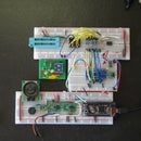
Step 3: The Circuit Board


All of these wires needed to go to resistors, and then to the USB cord. I decided to make a quick custom board. The power came in one end. Then a resistor went to each branch. For the green leds I used a smaller ohm resistor. For the yellow/orange, I tied them all to the same resistor.
I used nail polish to sketch out the pattern on a board. Then it was etched and drilled.
This was overkill. You could have used perf board, or even soldered the resistors directly to the wires and then used a wire-nut to connect the power to the USB cord.
Step 4: USB Power

My USB cord came from a broken keyboard, but you could buy one and cut the end off that you don't need.
The internet says that red should be +5 and black should be ground, green and white are for data. My first attempt I tried that and nothing worked. Since I had been testing the circuit every step of the way, I knew the problem was with the cord. Eventually I figured out that the white was ground. It helps to have a continuity tester or voltmeter.
I didn't want to plug this creation into my laptop untested, so I used a bench top power supply I'd built. It is handy to have a 5 volt power supply with a USB plug sitting around.
Otherwise the recommendation would be to use a powered USB hub. That would give you a little protection to your more expensive laptop.

Participated in the
Hardware Hacking

Participated in the
Make It Glow Contest

Participated in the
Manly Crafts Contest


