

Introduction: Chuck TV Intersect Cube DIY Working Model


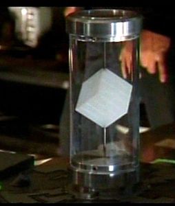


In season 2 (2009) we got to see the Intersect - a white translucent cube spinning inside a long vertical cylinder, its called the "Intersect Cube. "
Motivation: As a fan of the show I wanted my own working Intersect Cube - but for a lot less money than the official TV show version.
Design Approach: Based on the images from the TV show - a white cube spins inside a long plastic cylinder with two nicely machined aluminum caps top and bottom. Cube and cylinder assembly sits on a round metal base with four blue lights shining on the cube as it spins.
It probably cost the show producers several hundreds if not thousands of dollars to make and required a good machine shop. For my replicate I down sized to 9 inches diameter by 12 inches tall (probably about 2/3 the size of the one used on the TV show) and simplified the design so it can be produced for less than $100 using commonly available materials & tools.
[1] The "Simple Controller" includes an on/off switch and speed control knob. It requires just a little bit of soldering. The total material cost when built this way is probably < $70.
[2] The "Full Function Controller" features a PICAXE 08M micro ($4) talking to your PC, touch to activate sensor, and programmable speed control. It requires construction of a more complex electronic circuit. Using a Visual Basic App running on your PC, it can more or less simulate the entire "Intersect uploading sequence" as seen in Chuck TV episode Chuck vs the Ring. This includes uploading and playing an Intersect image video on your PC screen ... see if you "flash" afterwards.
http://www.youtube.com/watch?v=pRGJXG5yQCA
Step 1: Do Yourself a Favor
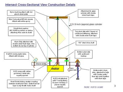
Construction Overview - You will find it VERY HELPFUL to review the attached PDF file of construction overview diagrams before beginning this project.
I apologize in advance for mixing inch and millimeter (mm) units ... I just find it easier to use mm when resolution better than 1/8 inch is required.

Step 2: Stuff You'll Need
The PDF file shows 3 parts lists. If you're planning to build your Intersect cube using the Simple Controller follow list "A" and "B." for the Full Function Controller, use lists "A" and "C."
The first item you should get: Get the glass cylinder first as you'll need to take some cylinder measurements to make sure everything fits together properly. You might also want to get a spare cylinder in case you break or mess the first one up. I had a problem with my local craft store switching brands, so I couldn't get an exact replacement.
Tools - Since you'll be cutting several items out of aluminum flashing, make sure you have good tin snips. If you're building the Full Function Controller, you'll need a fine point soldering iron.
Attachments
Step 3: Molding the Wax Intersect Cube

This is probably the hardest part of the whole project. The problem is that it is very hard to drill a hole precisely from one corner of a cube to the opposite corner. To get around that problem, we're going to "cast-in" the corner-to-corner hole using a metal tube.
1. The basic mold is constructed from a 10 oz waxed paper carton. I used the "Minute Maid" OJ container from Burger King - you'll need two cartons. Although the carton holds OJ just fine, it will leak when you pour hot wax in. To prevent this - smear Goop on the bottom of the carton, and then make a "diaper" using plastic wrap ( I used Reynolds Seal-Tight), use duct tape to hold the wrap to the outside of the carton. Cut off the very top of the container - you'll need maximum height to compensate for the sink-hole that forms as the wax cools, see additional comments below.
2. The container is too large at about 56 mm square, so you'll need to "pad " two of the inside walls with cardboard or foam board. I padded the walls to reduce the cube size to about 45 mm square, which fits inside a cylinder with 83mm inside diameter with OK clearance.
3. After you pad the two walls to reduce the size, line the padded walls with waxed paper cut from another carton. The basic idea is that all inside surfaces of the mold need to be waxed paper.
4. Cut the small metal tube (1/8 inch inside diameter) to a length about equal to the corner-to-corner distance and test it by positioning it diagonally inside the mold - this will create your corner-to-corner hole in the cube. Measure from the floor of the carton to the very top of metal tube, you want is dimension to to exactly equal to the cube side length, say 45 mm using the example given above. You'll probably need to cut and measure a few times to get it right.
5. After you have the tube length just right, glue the ends of the tube to the walls of the carton with Goop and let it cure overnight - you don't want it coming loose when you pour the hot wax..
6. Use a double pan arrangement to melt the wax, this means the pan with the wax sits in another pan of boiling water. You need to melt enough wax to fill the carton up to the very top because as the wax cools a deep sink-hole will form. After pouring the wax, let it sit overnight to be sure it cools completely.
7. Using a utility knife cut the carton away from the wax. Use a electric drill and a bit slightly smaller than the tube inside diameter to carefully clear out the wax that has accumulated inside the tube. Next use a hack saw to cut of the top portion where the sink hole formed. You can use a hot pan to melt away a bit of the wax cube sides to make minor corrections to the cube's shape - be carefully as it's very easy to melt away too much.
8. Finally using a knife, score a 4 by 4 grid on each cube side, this will create 16 little squares on each cube face. Set the cube aside for now, we'll attached it the the drive shaft a little bit later.
Step 4: Make the Base Plate


1. Cut 1/2 inch plywood into a 9 inch diameter circle. Cut aluminum flashing sheet stock material into a 9 inch diameter circle. Trim the outside edges with aluminum tape, see photo. Apply Goop to the plywood top surface and glue the aluminum 9 inch disk in place.
2. IMPORTANT: Next determine where on the disk to drill the 3, 3/16 inch holes for the rubber grommet screws. The 3 rubber grommets at all located on a "bolt circle" centered at the motor drive shaft, each screw is 120 degrees apart on that bolt circle. The 3 rubber grommets attach the cylinder to the base plate by squeezing against the inside wall of the the glass cylinder at three locations 120 degrees apart. The squeeze at each locations tends to even out doing a nice job centering the cylinder around the motor drive shaft. Warning - it is possible to get too much squeeze which can crack the glass.
To help assure the rubber grommet screws are located so as to give the correct squeeze against the cylinder, carefully measure the inside diameter (ID) of the glass cylinder, and the outside diameter of the rubber grommets (OD). We want the bolt circle to be large enough to assure the cylinder compresses the grommets just a little bit (see photo) when it is installed. Calculate the bolt circle (BC) using the below formula.
BC = (ID-OD) + 2 mm.
For example, if ID = 83 mm, OD =14 mm, then
72 mm Bolt Circle = (83-14) + 3
I recommend testing this bolt circle by drilling three holes at that BC in a scrap piece of wood to verify correct squeeze. See photo for how to assemble the 3 grommet & 8-32 thd, 1.5 inch long screws .
If the fit is good, then drill the real base plate the same way, else adjust as needed..
3. After the Goop cures, make the locations for the drilled holes in the disk as shown in the Drill Pattern PDF. The PDF is a full size template, so be sure to select NONE for Page Scaling when you print it out.
4. Note that if you're just making the "simple controller" you do not have to drill the touch sensor wire hole (but there is no harm done if you do drill it. The touch sensor 1/4" diameter hole needs to a drilled at a distance equal to 1/2 the outside diameter of the glass cylinder from the center of the base plate.
5. When drilling the holes, start with a drill bit no larger than 1/8 inch diameter, and then gradually enlarge the holes from there as needed. If you try to drill too large a hole all at once, the drill bit will likely snag on the sheet aluminum and make a mess of things.
6. With all the holes drilled, install the 1/4-20 T-nuts into the wood side of the base plate and use a hammer to seat them fully. Thread the 3, 1/4-20 2/1/2 inch long hex head bolts into the T-nuts. You want just a few threads sticking out above the aluminum side of the base plate - install an acorn nut on each of the threads. Adjust the amount each bolt is screwed in so the base plate sits level, then tighten the acorn nuts.
7. You can now install the three grommet mount screws.
Attachments
Step 5: Motor and Drive Shaft

1. Use progressively larger drill bits to drill out the pilot hole in the motor drive shaft so that it is enlarged to 1/8 inch diamater (see photo). Use care to assure the larger hole is still well centered in the motor drive shaft
2. Solder the motor connector wires, see photo to make sure you get the polarity right.
3. Measure and record the inside depth of the cylinder, add 1/8 inch to this dimension, and cut the 1/8 steel rod to that length.
4. On one end of the drive shaft, about 1/4 inch from the end, begin building up the diamter using heat shrink tubing until it's just a little less than the motor shaft dia. The final piece of heat shrink tubing should be longer so that it extends all the way to the end of the shaft. It should fit tightly on the motor shaft. This creates a flexible coupling between the motor and the 1/8 inch drive shaft.
Important -So that the drive shaft can be easily removed from the motor, only heat the top portion of the heat srink tube to bond it the the drive shaft, but not to the motor's shaft.
5. On the other end of the drive shaft, file or grind a nice bullet nose - this is just to make it easier to fit the shaft into the bushing (that is the bushing that is attached to inside closed end of the glass cylinder, see step #6) during final assembly.
6. Next take the 3-48 threaded rod and bend it into a U-shape. The span between the legs should match the two small mounting holes in the motor and the length of the straight portion of each leg should be about 1 3/4 inches. You want the legs somewhat long so that you can lower the motor the make final assemble easier.
7. Thread two nuts up towards the top of the U-bolt, and install the U-bolt thru the holes in the base plate. Then mount the motor to the base plate bottom and secure with two more nuts.
Attachments
Step 6: Cylinder


Attaching the drive shaft bearing ....
1. From sheet aluminum, cut a round disk sized to fit down inside the glass cylinder, almost all the way to the bottom (that is the closed end of the cylinder).
Since the glass cylinder inside is tapered, I used manila file folder material to cut test pieces until I got a good fit between the cylinder wall and the disk - then I cut the real one out of aluminum.
2. Make a hole in the center of the aluminum disk for the nylon flange bushing. Attach the bushing with hot melt glue or a small piece of tubing pressed onto the back of the flanged bushing.
3. To space the disk/bushing assy out from the bottom face of the glass cylinder cut 3 slightly smaller disks from cardboard and glue them together to form one thick stack. Cut a large opening in the center to provide clearance for the bushing.
4. Apply double stick tape to both sides of the cardboard disk pack. Attach the disk pack to the bottom of the cylinder, and then attach the disk/bushing assembly to the other side of the cardboard pack. It's important to assure the bushing ends up centered within the cylinder
Adding aluminum top and bottom bands ...
5. Apply double stick foam tape to the outside top and bottom portions of the glass cylinder.
6. Cover the outside end of the cylinder bottom (closed end) with a couple of strips of aluminum tape. (see photo)
7. Top Band Instructions - The "top band" attaches to the closed end of the cylinder (normally the bottom of the cylinder.) Cut a 22 mm wide band of aluminum strip long enough to wrap completely around the top band of double stick tape - cut it a little on the long side so there is about 1/2 inch of overlap that you can tape down with aluminum tape.
8. Bottom Band Instructions - If you're going to use the Simple Controller the bottom band is just the same as the top band.
Special Instruction for the Full Function Controller (Touch Sensor). The bottom band is actually the "touch activation" sensor. This means you need to attach a wire to the aluminum band which will be routed thru a hole in the base plate to the controller board.
Cut the band extra long so that you can cut a taper it at one end. Sand down the inside aluminum band surface to provide good electrical contact and then "roll and crimp" one end of 12 inch long length of stranded wire to the band end (see photo). Cut a 1/2 " gap in the double stick tape to create a pocket for the crimp/wire to "fall" into.
Finally, attach the band to cylinder using the double stick just as you did with the top band and tape the overlap down with aluminum tape.
To the other end of the sensor wire solder a one pin male header (see photo).
Step 7: LED Mounting and Wiring


1. Prepare 4 LEDs by cutting down the LED leads so they are about 1/2 long, but be sure to keep the positive lead a little longer than the negative lead just like it was originally. Solder about 10 inches of hook up wire to the LED leads, use a different colored wire for positive and negative leads. Apply heat shrink tubing to the solder joints.
2. Cut the 1/2 inch dia. plastic tubing at about 30 degrees on one end such that the LED light will strike the middle of the cylinder. The overall length of the tube should be kept as short as possible - just long enough to hold the LED.
3. Wrap the LEDs with double sided tape, but do not remove the outer paper tape layer - this will make it easier to slide the LEDs into the plastic tube (see photo).
4. Slide the LEDs into the tubes and bend the wires to go thru the 1/4 inch holes drilled in the base plate. Position the LED/Tubes so they point at the cylinder . The base of the tube should extend nearly to the outer edge of the base plate. Attach the tubes to the base plate using a hot glue gun.
Step 8: Final Trim Items, Cube Attachment, and Test Assembly

1. Bottom Skirt. Next we'll prepare a metal skirt to go around the three "leg" bolts located at the underside of the base plate. Cut a band of aluminum band about 44 mm wide and 27 inches long.
2. Apply poster mount putty to the outside portion of the three 1/4-20 bolts that serve as base plate legs. Wrap the aluminum strip into a nice circular shape around the 3 bolts - the putty will help the strip stick to the legs.
3. Where the strip ends join, use a large paper clip and aluminum tape to fasten the ends together. You will also need to cut an opening in the strip large enough to accommodate the power supply jack and on/off switch or RS-232 cable depending on which controller you're planning to use (see photos).
4. Bottom Disk. The bottom disk sits inside the glass cylinder resting on the heads of the 3, 8-32 rubber grommet mounting screws. Its job is the hide the screws and help create the appearance on a solid disk at the bottom of the glass cylinder.
5. Cut a aluminum disk with an outside diameter (OD) sized to fit inside the cylinder about 1 inch in from the open end. The disk inside diameter (ID) should be about 1/2 inch, it does not have to be perfectly centered as the cover washer (described below) will hide any off center errors..
6. Then cut a cardboard disk about the size as the aluminum disk and glue the two disks together - the cardboard just serves to stiffen the aluminum disk.
7. Cover Washer. The Cover washer goes over the drive shaft below the wax Intersect Cube and rests on the top of the Bottom Disk described above. Cut from aluminum strip stock a washer with 1" OD and 3/16" ID. Its job is just to mask any not quite centered errors between drive shaft and the bottom disk.
8. Attach Wax Intersect cube to Drive Shaft. First assemble the cylinder to the base plate and measure the distance (D1) from the base plate up the upper edge of the bottom 22 mm wide aluminum band you attached to the cylinder in Step 6. Next measure the distance (D2) from the base plate up the lower edge of the top 22 mm wide aluminum band.
Now remove the glass cylinder and and install the drive shaft on the motor and hold the drive shaft straight up. Mark the locations D1 and D2 (measured from the base plate) on the drive shaft. The wax cube should be centered half way between the D1 and D2 marks, this will center it in the "window" of the glass center created by the top and bottom bands.
10. Important - Before you glue the Wax cube in place. Slide the cover washer onto the drive shaft so that is rests on top of the drive shaft heat shrink tube coupler and below the final location were the wax cube is attached to the drive shaft (see photo). Glue the wax cube to the drive shaft using white epoxy - let sit overnight to fully cure. Finally, paint the exposed portions of the drive using a black magic maker.
11. Test fit Assembly. After the epoxy cures assembly the cube/drive shaft, bottom disk, and glass cylinder onto the base plate to make sure it all fits together as it should.
It can be a little tricky to get the top of the shaft fit into the nylon bushing, but by carefully tilting the glass tube and base plate assembly back and forth you should be able to get it assembled OK.
If you're really struggling ,you can loosen the motor mount nuts enough to drop the motor way down - this will allow the glass cylinder to be fully seated against the base plate, you can then grab the motor to move the drive shaft up and into position.
After test fitting everthing together, you can now dis-assemble to make it easier to complete the controller assembly on the bottom side of the base plate. Once that's done just re-assemble one final time.
Step 9: Building the Simple Controller


1. First solder the LED lead wires together per the circuit diagram. Insulate the solder joints with heat shrink tubing. Make sure you have the correct positive (red) and negative (black) wires going to the connector - the LEDs won't light up if the polarity is reversed.
2. Solder together the on/off switch, 22 ohm resistor, 25-ohm rheostat, DC power jack, and male part of the motor and LED connectors per the circuit diagram. The most important part is the making sure of the correct polarity.
3. Attach the on/off switch, 25-ohm rheostat, and DC power jack to the base plate with double stick foam tape. The on/off switch and power jack should be located near the outside edge and be visible thru an opening in the metal skirt going around the legs (1/4-20 bolts) of the base plate.
4. Reassemble the glass cylinder, wax cube, and drive shaft and any remaining components. Plug the 6 VDC power supply inotothe DC jack and hit the on switch. Adjust the rheostat to achieve the desired cube rotational speed.
That's it - you're done !
Step 10: Building the Full Function Controller


1. First solder the LED lead wires together per the circuit diagram. Insulate the solder joints with heat shrink tubing. Make sure you have the correct positive (red) and negative (black) wires going to the connector - the LEDs won't light up if the polarity is reversed.
See attached Controller Circuit Diagram.pdf. Most of the circuit is from pg 121 of "Programming and Customizing the Picaxe Microcontroller," by David Lincoln.
I can't provide complete details on the construction, but here are a few hints
2. QT113A-ISG, Mouser.com item# 556-QT113A-IGS is the touch sensor IC. It is a surface mount part since the DIP package is no longer available. To make it easier to connect it to the prototype PC board (Radio Shack 276-150), I mounted the IC on a SO8-SMD to DIP Adapter.
The adapter mini board solder pad locations are pre-tinned were the IC legs attached, so it wasn't as hard to solder as I thought. However ,the adapter is so wide that I soldered some jumper wires under it to help save space.
3. The Run/PRG switch could be replaced with a simple jumper block, since in theory you should only have to switch modes once for the initial Picaxe program down load.
4. I hard wired in the RS-232 cable directly from the PC board to a 9 pin female connector. It then plugs into the RS-232 COM port on my PC.
If you need a USB serial connection instead, you'll need to get Picaxe special cable AXE027. The cable has electronics built in to make USB signal "look" just like RS-232 to the Picaxe chip. AXE027 requires a 3.5 mm jack at Picaxe chip end, see Picaxe website for more details.
http://www.rev-ed.co.uk/picaxe/
5. A combination of double stick foam tape. hot glue, and velcro attach the completed PC board, DC power jack, and RS-232 cable to the bottom side of the base plate.
6. The circuit does not have an on/off switch, it's always powered on awaiting a command from the PC to stop or start. You can of course disconnect the power plug from the DC jack.
7. Don't forget to connect the touch sensor wire to the PC board when you assemble the cube and cylinder to the base plate.
Attachments
Step 11: Programming the Full Function Controller

Firstly, I need to give credit to John Moxham, who published an instructable that showed how the Picaxe can talk with a PC running a Visual Basic program.
I based much of my design and especially the VB code on his work, see the following link ...
https://www.instructables.com/id/Automate-your-science-experiments/
John's instructable also gives more details on building VB apps over and above the very brief instructions I give below. I built John's complete project before I even started mine - it's what gave me the confidence I could do it.
1. Download the Free Picaxe Programming Editor Software from -
http://www.rev-ed.co.uk/picaxe/
2. Install the software on your PC and connect the serial cable from the Full Function Controller to your PC. Set the Run/PRG switch to PRG, and connect 6VDC power supply.
There are a few initial settings (like Com Port) to be done in Picaxe Programming Editor Software, see the Help menu, especially "Manual 1 - Geting Started."
3. Use the FILE>NEW menu command to open a new window and then copy and paste in the below code:
..............................................................................................................
input 4 ' touch switch equals 0 if touched, else equals 1
b2=1 ' inital variable value for touch switch on/off state: 1 = off ,0= on
main:serin 3,N2400,("Data"),b0,b1,b2,b3,b4,b5,b6,b7,b8,b9,b10,b11,b12,b13
b2 = pin4
serout 0,N2400,("Data", b0,b1,b2,b3,b4,b5,b6,b7,b8,b9,b10,b11,b12,b13)
if b2 =0 and b1 = 1 then 'REM b1 is the ready to activte flag set in VB program
b0=3
endif
select case b0 ' determines how to run motor and LED on/off state
case 0
low 1
pwmout 2 OFF ' LEDS and motor both off
case 1
high 1
pwmout 2, 255, 350 ' LEDS on and motor at idle speed geeting ready for activation
case 2
high 1
pwmout 2, 255, 450 ' LEDS on and run motor at medium speed for test run
case 3
high 1
pwmout 2, 255, 700 'LEDS on and motor at full speed in activation & upload mode
else
low 1
pwmout 2 OFF ' LEDS and motor both off
endselect
goto main
........................................................................................................
4. Click the Little Blue Triangle on the menu bar to download the program.
5. If you didn't get an error message during the download you're done.
If you are really stuck at this stage, ask for some help at the Picaxe help forum http://www.picaxeforum.co.uk/
The Full Function controller won't do anything it this point. So just reset the Run/PRG switch to RUN, and disconnect 6VDC power supply & serial cable.
Step 12: Installing/Running the Visual Basic Code on Your PC


Just Google " Visual Basic Express 2008 download"
The download is pretty big and will include the .NET framework software if it finds you don't already have that on your machine.
The important thing is to make sure the Visual Basic installation is complete and you can open the VB programming environment on your machine (see photo).
2. Download to your hard drive the .wmv file, this is the Intersect Video file. This file was provided to me courtesy of You Tube User Buzz100165.
Also download and print out the file User Interface.pdf .
3. Download the attached .zip file and un-zip everything to a sub directory on your PC's hard drive.
In Explorer find the file ...
Name = Intersect Cube & File Type = Microsoft Visual Studio Solution,
double clicking on that exact file should launch the application in Visual Basic Studio Express. It takes a little while to load the first time.
4. Make to following connections: 6 VDC power supply to Full Function Controller DC power Jack, and serial Cable between Full Function Controller & your PC.
5. You are now ready to begin your first test. In VB express, click on the little green triangle (see photo) to run/debug to application. If all goes well, you should, after a little while, see the main INTERSECT application screen.
Refer to User Interface.pdf to test the program.
The initial "Time Out "error should go away after you select your Com Port.
For Select Intersect Data File, you need to select the .wmv file you downloaded in step 3 above.
First test manual operation using the STOP and TEST RUN buttons. If that works OK, then ... hit the "INITIALIZE INTERSECT FOR UPLOADING" button.
When first clicked, the cube will spin slowly. It’s waiting for you to touch the lower cylinder aluminum band to “activate it”.
Touching the band for a second or two, should start the cube spinning faster and begin the activation sequence, after that it will start the upload sequence which includes playing the selected Intersect Video File in full screen mode.
When it finishes, the cube will return to spinning slowly. You can then click to stop button.
Unfortunely, if you go thru the above sequence a second time, the Intersect video fails to play in full screen mode. You can fix this by exiting and restarting the application. I have not yet figured our how to fix this. See additional comments in the Conclusion & Improvements Step.
6. That's it - pat yourself on the back for a job well done.

Step 13: Conclusions Next Steps
The hardest part of this project was molding the wax cube and programming the Visual Basic Application - mostly getting the Windows Media Player stuff working right. See problem described at the end of step 12. On the plus side, as this was my first VB program, I did learn a lot about modern programming methods.
I have enough stuff left over to make a second Intersect Cube - planning a model that takes advantage of the Picaxe built in ability to read 127 Sony IR codes with a very simple & cheap circuit. This means I can control it from across the room using a universal remote control.
Also thought about a Picaxe program #2 that would allow the Intersect Cube to operate stand alone without being connected to a PC. This should not require any hardware changes, just disconnect the RS-232 cable and reprogram the Picaxe to say start up when the touch sensor is touched and then turn itself off after say 10 seconds.
I would also like to make my own Intersect style video, but instead of government secrets as the subject matter, use images from the Chuck TV show itself. It tried making a movie from jpegs images with QuickTime, but it didn't look all that good.
If anyone has ideas on how to make the cube itself that you be easier than the wax mold process that would be great.
Thanks for taking a look at my Instructable.


