

Introduction: Color Sensors and Arduino Serial Communication for Beginners


Hi all, I'm going to talk about color sensors: how to build and calibrate one and how to use it with serial communication through an Arduino board.
The last step explains how I used this project for a Gimp (stands for "GNU Image Manipulation Program", here the official website: http://www.gimp.org/ ) plug-in. This plug-in works only on GNU/Linux machines so, most of you, probably can't use it. I firstly wanted to program the plug-in for Windows, but since that I'm a complete newbie in serial communication programming on that OS, I opted for Linux. The functioning of the plug-in is explained in the last three pictures of this step.
NOTE: As an European I express lengths in cm. I'm sorry for north American readers.
NOTE #2: Sorry for bad English. English is not my main language.
Step 1: Materials

For this project I've used
- 1x Arduino UNO board
- 1x RGB common anode LED
- 1x Photoresistor (LDR4)
- 1x 220Ω resistor
- 1x 10KΩ resistor
- 1x 10μF electrolytic capacitor*
- Cardboard (I've used 4x4cm of it)
- Black paint
- A paint brush
- Wires
- An USB cable*
- Heat shrink tube*
- A lighter*
- A computer with Arduino IDE* (Optional for the last step: a GNU/Linux machine with Gimp installed)
- A pair of scissors*
- A pencil*
- A needle*
"*" stands for "Not in the picture"
The total cost of the project, excluding the computer, the Arduino board and other stuff (like paint brush, lighter, scissors, pencil and so on), is about 5€.
Step 2: The Color Sensor


How does a color sensor work? It rests on the principle that we see things because they reflect light. But light, the white light, the sun light, is made up by the seven rainbow's colors together. The colored objects don't fully reflect all the 7 colors they receive but they absorb some of them: in this way, to the human eye, a banana is yellow because it absorbs all the colors except the yellow. So, a color sensor is typically made up by an RGB LED and a photoresistor: while the LED flashes red, green and blue, the photoresistor reads how much red, green and blue light the object that the sensor is reading reflects.
Let's make the color sensor:
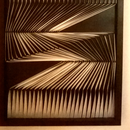
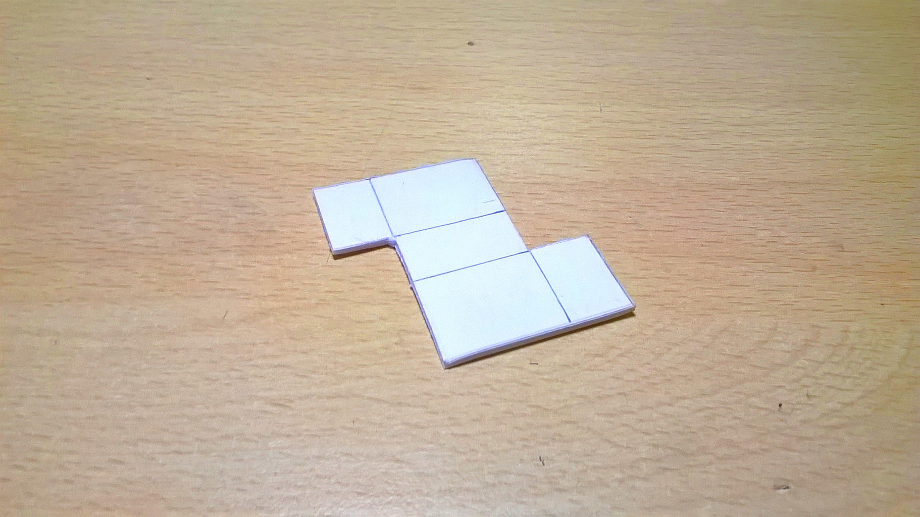
Take the cardboard, cut out the pattern [Pictures 1, 2 and 3], fold the piece following the lines (Be careful, is not easy to fold accurately such a little piece of cardboard.) [Picture 4] and paint it black [Picture 5].
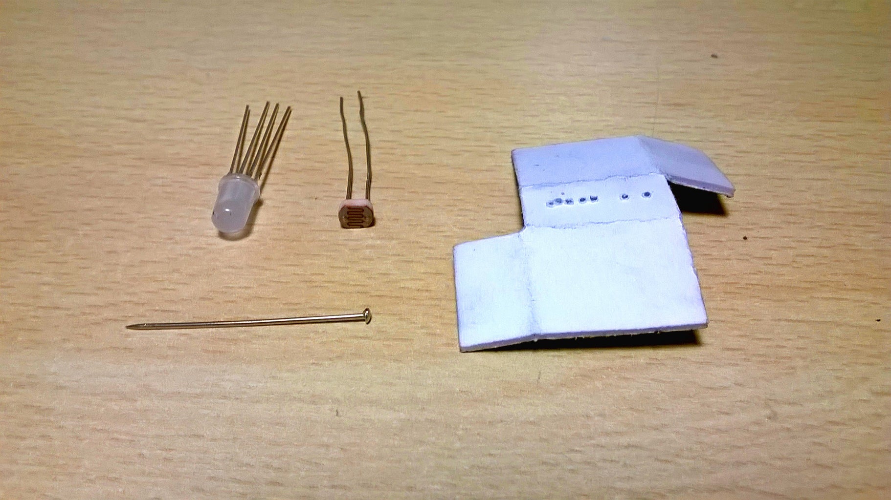
Now, make six little holes on the piece of cardboard with a needle: four of them are for the RGB LED pins (make them very close to each other) and the other two are for the photoresistor [Pictures 6 and 7].
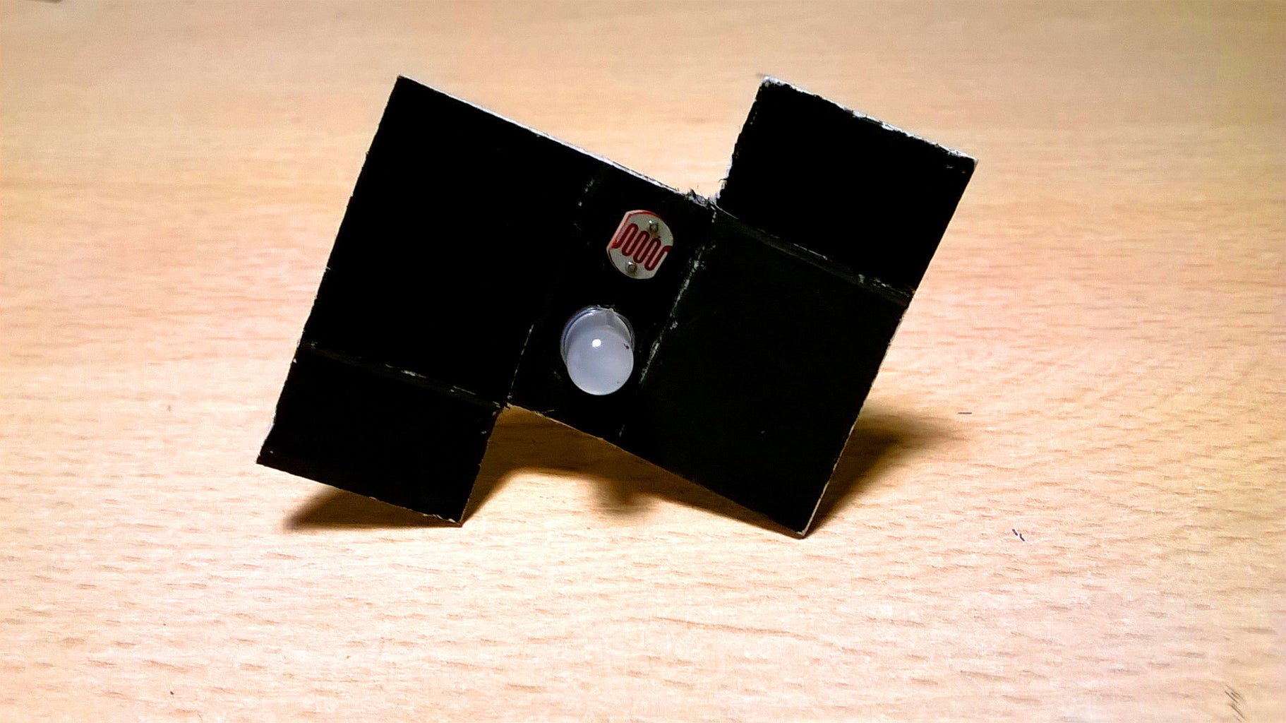
Insert the LED and the photoresistor in their places [Pictures 8 and 9].
Cut a 6x1.5cm strip from a sheet of normal printing paper [Picture 10]. Put glue on one side of this stripe [Picture 11] and stick it to the sensor in order to "close" it [Pictures 12, 13 and 14].
Fix their position with heat shrink tubes [Picture 15]. It is essential fixing the position of these two components: if they are free to move, the readings from the sensor will not be faithful. Please note that in picture 15 there is an error: the two pins of the photoresistor touch themselves. This must not happen (I've struggled a lot to figure out what was the problem when testing the sensor).
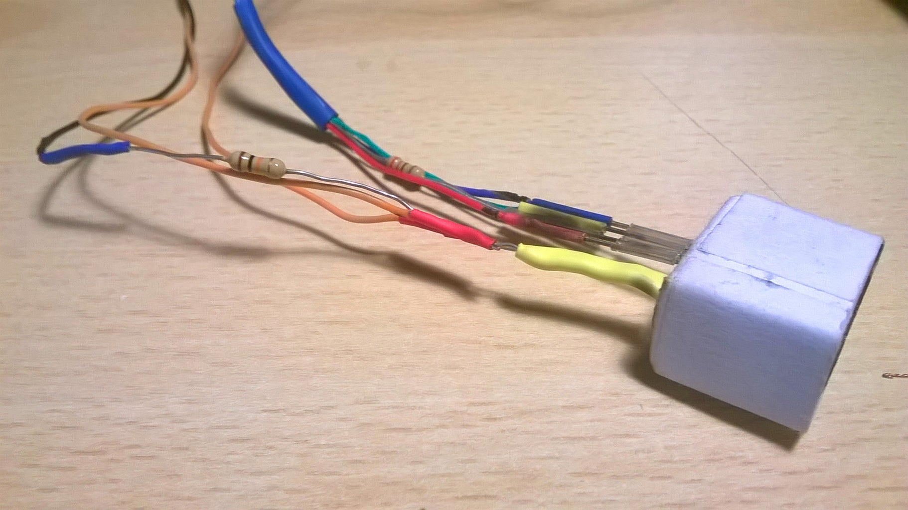
Finally, following the scheme in picture 16, connect using the shrink tubes (or solder if you want, officially soldering is better) wires and resistors together. My final product is shown in the last two pictures.
Step 3: Connect the Sensor to Arduino and Calibrate


Connect the sensor to the Arduino as shown in picture 1: the red wire to pin 8, the green one to pin 9, the blue one on pin 10, the LED anode and the right photoresistor's pin to 5V, the left photoresistor's pin (the orange one) to A0 and the other right pin (the one connected to the 10KΩ resistor) to ground.
Upload the calibrateColors.ino sketch into the board. Pick an opaque white object and put the sensor on it. While keeping the sensor in place open the serial monitor in the Arduino IDE: you should see something like the picture 2. Write down these values. Now place the sensor on a opaque black thing and write down these new values. Close the serial monitor.
Open the colors.ino file in the IDE and replace the values read by your sensor to mine in lines from 8 to 14 in the sketch.
E.g.: In the colors.ino file that I've uploaded there are these lines:
#define R_MIN 460
#define G_MIN 190
#define B_MIN 147

#define R_MAX 762
#define G_MAX 470
#define B_MAX 392
If your sensor, when placed on a white surface read:
r: 892 g: 527 b: 370
and when on black:
r: 495 g: 219 b: 131
your colors.ino lines from 8 to 14 will be:
#define R_MIN 495
#define G_MIN 219
#define B_MIN 131

#define R_MAX 892
#define G_MAX 527
#define B_MAX 370

Step 4: Upload the Final Sketch and Enjoy

Upload your calibrated version of colors.ino into your board.
Now, pick the 10μF capacitor and put its negative pin to ground and the other
pin into the reset pin as shown in picture 1. This capacitor is used to disable the auto-reset that occurs when a serial communication is established between the Arduino and a computer. Remember to pull this out when you want to upload new code into the board.
For reading colors you have to:
- Connect the board to a computer
- Open Arduino IDE
- Open the serial monitor
- Place the sensor on the thing you want to scan
- Type a letter into the serial monitor and send it to the board
- Read the HTML color code that the board sends back
- Repeat on other objects
Step 5: Gimp for Linux Integration
The project is finished even without this step, but, if you have a GNU/Linux machine, this will make this color reader a lot more cool.
colors.c is a plug-in for Gimp that works only on Linux. It simply sends a byte to the Arduino when the "Read color from sensor..." button in the menu's "Color" section is clicked and, when the Arduino answers, it reads the color code and sets it as new foreground color.
The capacitor between ground and the reset pin is essential here, because the plug-in opens a new serial connection every time the "Read color from sensor..." button is clicked, and, if the auto-reset is not disabled, the plug-in will read strange values.
Before you can install the plug-in you have to check if the Arduino board is connected to the /dev/ttyACM0 serial port. You can check this from the Arduino IDE: in the right bottom corner there must be written something like "Arduino UNO on /dev/ttyACM0".
If not, you must do some changes to line 116 of color.c file. The original line is:
fd = open("/dev/ttyACM0", O_RDWR | O_NOCTTY | O_NDELAY);You must replace "/dev/ttyACM0" with the address of the serial port on which the board is connected.
For example, if in the IDE there is written "Arduino UNO on /dev/ttyUSB2", the line in your colors.c file has to look like this:
fd = open("/dev/ttyUSB2", O_RDWR | O_NOCTTY | O_NDELAY);After this check you can simply install the plug-in by typing in a terminal emulator:
gimptool-2.0 --install /path/to/the/source/colors.c
This instructable ends here. I hope that you find this project interesting. If you have some questions don't hesitate to ask. Please leave feedback.

Participated in the
Mind for Design


