

Introduction: Compact Regulated PSU - Power Supply Unit


I have already make a few PSU. At the beginning I always assumed that I need PSU with lots of Amps, but during few years of experimenting and building things I realized that i need small compact PSU with stabilize and good Voltage regulation and current limiter, that didn't take to much space on my workbench.
Like in most of my project it all started with salvage components that came in my possession.
Friend of mine gave my transformer 230V/16V from the old alarm system which is the main component of mine PSU.
Step 1: Component List


1. Transformator 230V/16 V - 1,8 A
2. Original Hiland 0-30V 2mA - 3A Adjustable DC Regulated Power Supply DIY Kit
https://www.banggood.com/0-30V-2mA-3A-Adjustable-D...
3. Dual Red Blue LED Digital Voltmeter Ammeter Panel Volt Gauge Meter
https://www.banggood.com/Dual-Red-Blue-LED-Digital...
4. DC 12V -50 to +110 Temperature Control Switch Thermostat Thermometer
https://www.banggood.com/DC-12V-50-to-110-Temperat...
5. Heat sink with fan (24VDC)
6.Voltage stabilization IC 7812
7. Lot 3MM Silver Chrome Metal Plastic LED Light Lamp Emitting Diode Bezel Holders
https://www.banggood.com/Lot-3MM-Silver-Chrome-Met...
8. 3 x LED 3mm
9. 2 x Pot. knob
https://www.banggood.com/Potentiometer-Volume-Cont...
10. ATX shell
11. 24VAC power relay with 4 contact (NO-COM-NC) this is option for WELLER supply compatibility
12. Vinyl Wrap Roll
Step 2: ATX Housing Adaptation – Hardware Work


When I had all components at my hand it was time for space management inside of the PSU. Because I decided to use ATX power supply housing I have to manage everything very carefully and this space planning took me lot of time.
After everything was cool, I made a front label on my PC for easier marking.
Mostly it was just drilling, the hole for ampere/volt-meter I used small drill (don’t know how it is called)
At the bottom of the housing I have mounted four of stands that I demounted from old coffee maker
Handle on the back is from the old kitchen socket, mounted with two M4 nuts with washers :)
Step 3: Schematic
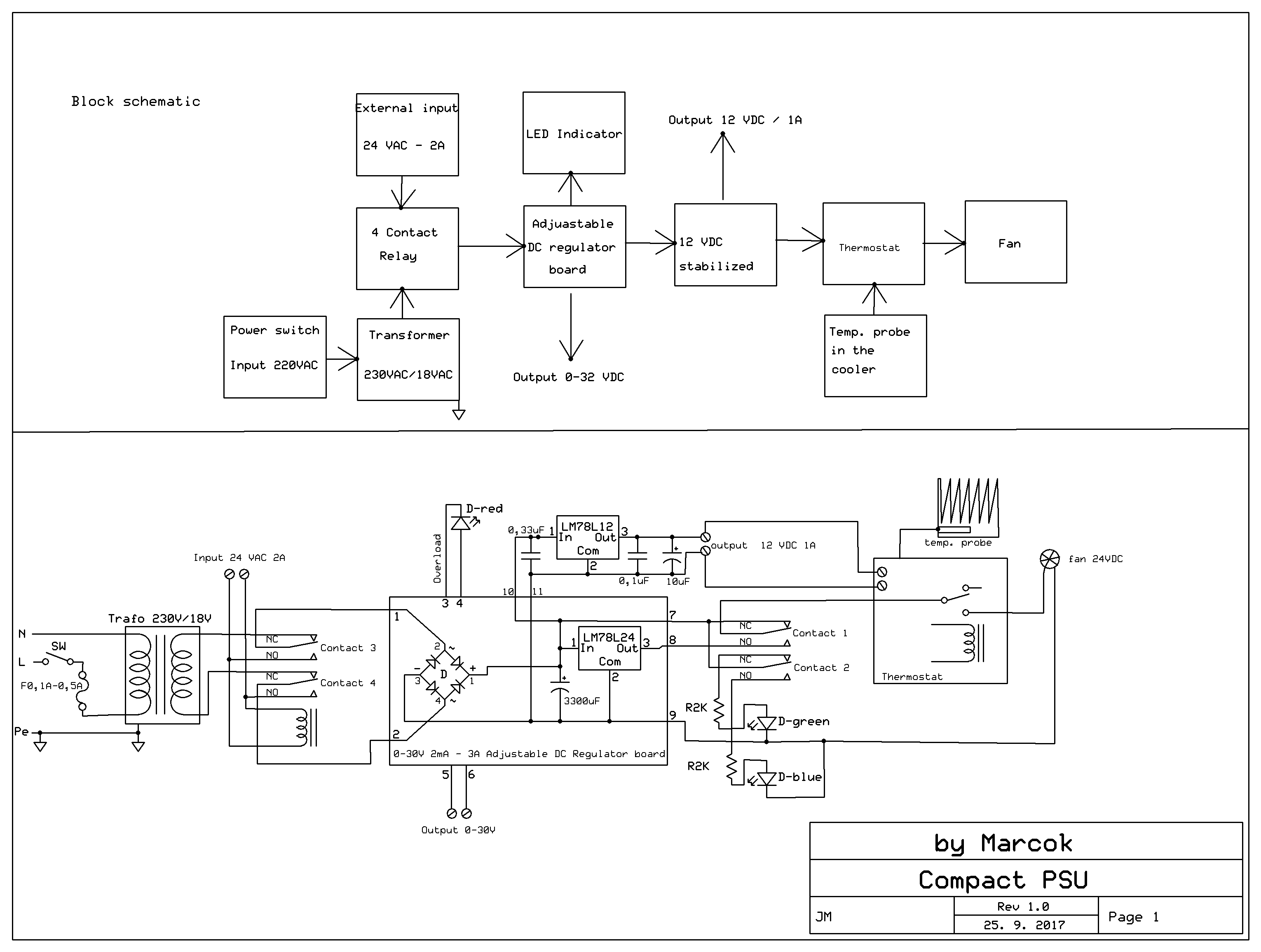


Here is schematic of the PSU (I’m not that skilled with drawing of the schematic, as you can see). If something is not clear please feel free to ask in comments, I’m realize that schematic could be done better and when I find some time I will upload better version.
I add thermostat for activating fan, when I use PSU on small current or on standby I don’t want to hear fan.
I have mounted transistor and voltage stabilization IC (7812), on the cooler.
I drilled hole for the thermostat probe into the cooler.
For mounting of the fan on the cooler I used 1.5mm copper wire and for fixing the fan and cooler onto the housing I used four 1cm standoffs.
Resistors for the LEDs are soldered directly on the 3mm LED and then isolated with shrinking tube.
Same principle is used for connecting the relays contacts
Step 4: Carbon Fibre Vinyl Wrap


I wanted to make a nice look for the housing, so I used Carbon Fiber Vinyl Wrap instead of painting. Also I got an idea that I could customize PSU with my signature :), I have cut my brand mark from the carton box and covered it with vinyl wrap, also I didn’t want to have unnecessary holes on the housing so I used carton box from my favorite cookies and cover the holes and also covered with vinyl wrap
Step 5: Front and Back Sticker


I wanted to have clear front panel, so I have design front panel on my computer (use which ever program you prefer) and printed out on printer. This is very convenient also for hardware part of drilling and cutting. Front of the sticker I have adhibit with see-through tape. Back of the sticker is adhibit with two-side tape and taped on the housing.
Attachments

Step 6: Mounting Components on Front Panel and in the Housing


When the housing were prepared I have started with mounting the elements on/in it. Housing consist of two parts, so for easy assembling there should be long enough wires for manipulation during the assembly.
Grounding the housing is very import, ATX usually have a ground connecting place inside the housing, check it on the photos
First I have mounted everything in the housing and start wiring everything together according the schematic. All of contacts are well soldered creating good and reliable contact and isolated with shrinking tube insulators.
Step 7: Calibration and Setting of the Thermostat


Amper/Volt meter have a small potentiometer (miniature) on the back of the panel meter, used for calibration.
After wiring everything all together calibration of the volt meter and ampere meter was necessary. With Volt meter is quite easy and accurate, I have low the voltage to the 4.5V and use the potentiometer on the back of the voltmeter to set it with my multimeter, I repeat this at 12V and 13.7V.
Calibration of the Ampere meter was little bit tricky, I have calculate current for the 5W bulb P=U*I , so that current should be at 12V I=5 / 12 = 0.416A . This is not first class ampermeter but I manage to set it nearest to the desired value, I repeat this step with 15W and 21W bulb and manage to calibrated to the nearest values, and compare this with my multimeter and it is precisely enough for normal and reliable use. Do not expect lab PSU precisely values….
Thermostat is set to activate fan at 40 C°, setting the thermostat is not very complicated and the precise instruction are on the site where I bought the thermostat. After two months of using is working ok.
Step 8: Interconnecting Cable for Weller Soldering Station


I have TCP-S Weller soldering station which have 50W /24VAC transformer what is perfect for my PSU. From old Weller handle I have harvested connector and made Interconnecting cable suitable for my PSU in case if I need more Voltage and juice.
As you can see on the schematic, for this purpose I have add 24VAC relay on the input, when the external source is added PSU automatically switch to this input what is signalized with blue LED on the front panel.
Step 9: Final Product


It is nice PSU with small dimension, it is working fine and I am very pleased with it. Any suggestion and improvements are welcomed.


