

Introduction: Connect Arduino Uno to Android Via Bluetooth

In this project a serial Bluetooth module is used to create a connection between Arduino Uno and an Android app that I created with MIT App Inventor.
Arduino listens for commands to light some LED's or show its status. In addition, a timer interrupt makes it check for temperature via a TMP36 sensor: if temperature is greater than a threshold a LED is lit; every n seconds (where n is a parameter set through the app) a status report is sent to the app. A simple command structure enables the app to send parameters and values to Arduino and the other way round.
There are many Bluetooth modules and even Arduino shields: my choice has fallen on JY-MCU that I bought from Hobby Components in the UK.
The JY-MCU is a class-2 Bluetooth module that acts like a serial port with no need of any software configuration on the Arduino. This module is available in several configurations, and this has been the first hurdle to overcome.
The one we need to make the connection between Arduino and the Android phone is a Slave Module. To make things very simple, there are two types of devices: Master and Slave; a Master can communicate with more than one Slave while a Slave can communicate with a single Master at a time, Master-Master and Slave-Slave communication is not allowed. Since the Bluetooth module in all smartphones is of Master type, the one we need for Arduino must be a Slave (this has nothing to do with client-server communication as we'll see later in the app description).
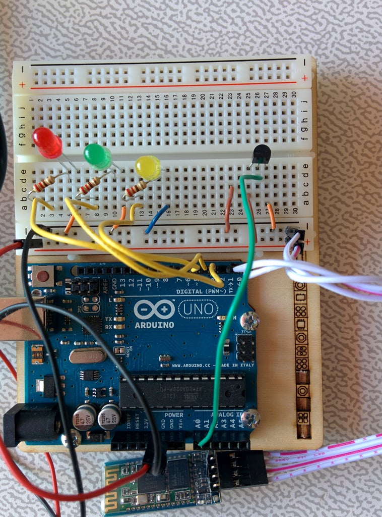
Step 1: The Circuit
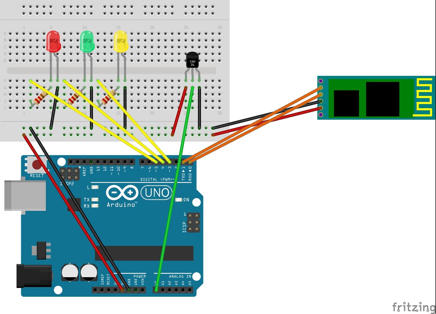
Components:
1 x Arduino Uno
3 x 220 Ohm Resistrors
1 x Green LED
1 x Yellow LED
1 x Red LED
1 x TMP36 Temperature Sensor
1 x JY-MCU Bluetooth Slave Module (see introduction)
1 x Breadboard
wires
Connections:
Step 1): Connect Ground and 5V from Arduino to breadboard.
Step 2): Place the LEDs on the breadboard and connect their catodes to ground; connect their anodes to Digital Pins through a 220 Ohm resistor each: Yellow to Pin 3, Green to Pin 4 and Red to Pin 5.
Step 3): Place the TMP36 sensor on the breadboard and connect its pins to 5V, Ground and A0 Arduino Pin.
Step 4): Connect the provided cable to the JY-MCU Bluetooth module on one side and to the breadboard to the other side; connections are as follows:
VCC <--> 5V
GND <--> GND
TXD <--> Pin 0 (Rx)
RXD <--> Pin 1 (Tx)
The sketch will also make use of Arduino built-in LED on Digital Pin 13.
The connections of the Bluetooth module can be a little confusing since TXD goes to Rx and RXD goes to Tx: here's an explanation. Transmit and Receive refer to each device, therefore a transmission coming out of TXD pin of the Bluetooth module must be received by Arduino on the Rx Pin 0; similarly a transmission going out of Arduino Tx Pin 1 must reach the JY-MCU Bluetooth module on its RXD pin.
Warning: The Bluetooth module may interfere with PC to Arduino communication: disconnect VCC when programming the board. (in my tests this has not been the case, but for sure it won't do any harm).
Step 2: Arduino Code - Introduction

Arduino listens for commands to light some LED's or show its status. In addition, a timer interrupt makes it check for temperature via a TMP36 sensor: if temperature is greater than a threshold a LED is lit; every n seconds (where n is a parameter set through the app) a status report is sent to the app. A simple command structure enables the app to send parameters and values to Arduino and the other way round.
The command structure defined in the program is:
CMD RED|GREEN|YELLOW=ON|OFF
CMD TMAX|SECONDS=value
CMD SECONDS=value
CMD STATUS
The Status message structure is:
STATUS RED|GREEN|YELLOW|TMAX|SECONDS|TEMP|THIGH=value
Arduino will answer to the STATUS command with full status while on interrupt it will report a shorter version.
Examples:
CMD RED=ON switches the red LED on
CMD GREEN=OFF switches the green LED off
You can test the sketch by issuing commands and viewing responses in Arduino IDE's Serial Monitor: make sure to select Carriage Return in the dropdown options at the bottom.
You can download the sketch code from the attached file. The following step will provide a detailed explanation of it.
Attachments

Step 3: Arduino Code - Details
Command and message structure as described in the previous step
// Serial Parameters: COM11 9600 8 N 1
// \r or \n to end command line
// Bluetooth is on Pin 0 & 1 @ 9600 speed
// Command structure // CMD RED|GREEN|YELLOW=ON|OFF
// CMD TMAX|SECONDS=value
// CMD SECONDS=value
// CMD STATUS
// Status message structure
// STATUS RED|GREEN|YELLOW|TMIN|TMAX|SECONDS|TEMP|THIGH=value
Initialization of variables needed for temperature control
float maxTemp = 30.0; // switch on led when temp > maxTemp
int maxTempSensor = (int) ((maxTemp / 100 + .5) * 204.8);
float temperature = 0.0;
maxTemp can later be changed, but the program needs a default value to start with. maxTempSensor is the conversion of maxTemp to the 0-1023 range provided by Arduino ADC converter; temperature comparison will be performed by an interrupt routine that we want as fast as possible: it is more efficient to directly compare the integer Pin output value rather than the float temperature. We still want to report the temperature and the program will store it in the variable with the same name.
If you are not familiar with the temperature conversion formula, you can have a look here.
maxSeconds can also be changed with a command but again we need a default
int maxSeconds = 10; // send status message every maxSeconds
Declarations of Pin constants
const int ledPin = 13; // temperature led
const int tempPin = A0; // T36 temperature sensor analog input pin
const int led1Pin = 3; // Yellow
const int led2Pin = 4; // Green
const int led3Pin = 5; // Red
Variables used in the interrupt routine and accessed from outside of it
volatile int tempVal;
volatile int seconds = 0;
volatile boolean tempHigh = false;
volatile boolean statusReport = false;
Volatile is a special keyword that prevents the compiler from performing certain optimizations: all variables that are modified within an interrupt routine and are also accessed outside of it must be declared as volatile to signal that their value can change at any time and to make sure the latest, correct, value is read from memory when needed.
Command string variables (they will be explained later)
String inputString = "";
String command = "";
String value = "";
boolean stringComplete = false;
The setup() function
void setup(){
//start serial connection
Serial.begin(9600);
Serial.print("Max T: ");
Serial.print(maxTemp);
Serial.print(" Sensor: ");
Serial.println(maxTempSensor);
inputString.reserve(50);
command.reserve(50);
value.reserve(50);
pinMode(ledPin, OUTPUT);
digitalWrite(ledPin, LOW);
pinMode(led1Pin, OUTPUT);
pinMode(led2Pin, OUTPUT);
pinMode(led3Pin, OUTPUT);
digitalWrite(led1Pin, LOW);
digitalWrite(led2Pin, LOW);
digitalWrite(led3Pin, LOW);
The reserve method of a string allocates the number of bytes provided as argument.
The following code is needed to initialize the timer interrupt and set it to fire every second, the slowest that Arduino can do; for detailed information see here.
cli(); // disable global interrupts
// initialize Timer1 for interrupt @ 1000 msec
TCCR1A = 0; // set entire TCCR1A register to 0
TCCR1B = 0; // same for TCCR1B
// set compare match register to desired timer count:
OCR1A = 15624; // turn on CTC mode:
TCCR1B |= (1 << WGM12);
// Set CS10 and CS12 bits for 1024 prescaler:
TCCR1B |= (1 << CS10);
TCCR1B |= (1 << CS12);
// enable timer compare interrupt:
TIMSK1 |= (1 << OCIE1A);
sei(); // enable global interrupts
}
The timer interrupt routine: we cannot change its name, but the content is entirely customizable.
ISR(TIMER1_COMPA_vect)
{
tempVal = analogRead(tempPin);
if (tempVal > maxTempSensor) {
digitalWrite(ledPin, HIGH);
tempHigh = true;
}
else {
digitalWrite(ledPin, LOW);
tempHigh = false;
}
The temperature value - or, as discussed above its 0-1023 integer representation - is read from the sensor and is compared with the the threshold value: when above the built-in LED is lit and tempHigh is set to true, otherwise the LED is switched off andtempHigh is set to false.
if (seconds++ >= maxSeconds) {
statusReport = true;
seconds = 0;
}
}
Remember that the interrupt is fired every second, but we want to report the system status less frequently: the seconds variable is incremented at each iteration until it reaches the values when the report is due; this will be done later in the main loop by checking statusReport flag. As a rule, never never perform something so slow such writing data to serial from within an interrupt routine.
The loop() function interprets and executes commands when received, it then reports status if flag is raised by timer interrupt. In order to read a string from the serial buffer, loop() relies upon the serialEvent() function that will be defined at the end: this routine is run between each time loop() runs. It is not widely documented and it probably doesn't apply to all Arduino models; in any case, it's not difficult to nest its content within the main loop (see the end of thi step).
void loop(){
int intValue = 0;
if (stringComplete) {
Serial.println(inputString);
boolean stringOK = false;
if (inputString.startsWith("CMD ")) {
inputString = inputString.substring(4);
First we check if the received string starts with "CMD ": if so we can discard the first four characters, otherwise we'll later raise an error.
int pos = inputString.indexOf('=');
if (pos > -1) {
command = inputString.substring(0, pos);
value = inputString.substring(pos+1, inputString.length()-1); // extract command up to \n exluded
There are two types of commands: those setting a value, where we'll find "=" separating the variable+value pair, and those where the command is a single directive (STATUS). If "=" is present at pos, the string is split into command (left part) and value (right part), dropping both the "=" in between and the end-of-line character at the end.
if (command.equals("RED")) { // RED=ON|OFF
value.equals("ON") ? digitalWrite(led3Pin, HIGH) : digitalWrite(led3Pin, LOW);
stringOK = true;
}
else if (command.equals("GREEN")) { // GREEN=ON|OFF
value.equals("ON") ? digitalWrite(led2Pin, HIGH) : digitalWrite(led2Pin, LOW);
stringOK = true;
}
else if (command.equals("YELLOW")) { // YELLOW=ON|OFF
value.equals("ON") ? digitalWrite(led1Pin, HIGH) : digitalWrite(led1Pin, LOW);
stringOK = true;
}
We examine and execute the LED commands; note that the code only checks for value ON: if you write GREEN=ASD it will be interpreted as GREEN=OFF. It's not perfect, but it keeps things a lot simpler. stringOK=true is set every time a command is recognized and executed so that wrong commands will be flagged later.
else if (command.equals("TMAX")) { // TMAX=value
intValue = value.toInt();
if (intValue > 0) {
maxTemp = (float) intValue;
maxTempSensor = (int) ((maxTemp / 100 + .5) * 204.8);
stringOK = true;
}
}
else if (command.equals("SECONDS")) { // SECONDS=value
intValue = value.toInt();
if (intValue > 0) {
maxSeconds = intValue;
stringOK = true;
}
}
When value should be a number, we need to convert it and test it really is a number. In the case of MaxTemp, we also compute the sensor value as explained in the variable definition section
} // pos > -1
else if (inputString.startsWith("STATUS")) {
Serial.print("STATUS RED=");
Serial.println(digitalRead(led3Pin));
Serial.print("STATUS GREEN=");
Serial.println(digitalRead(led2Pin));
Serial.print("STATUS YELLOW=");
Serial.println(digitalRead(led1Pin));
Serial.print("STATUS TMAX=");
Serial.println(maxTemp);
Serial.print("STATUS SECONDS=");
Serial.println(maxSeconds);
Serial.print("STATUS TEMP=");
Serial.println(temperature);
Serial.print("STATUS THIGH=");
Serial.println(tempHigh);
stringOK = true;
} // inputString.startsWith("STATUS")
If command is STATUS, the program simply outputs all information to serial.
} // inputString.startsWith("CMD ")
stringOK ? Serial.println("Command Executed") : Serial.println("Invalid Command");
Signal if a valid or invalid command has been received.
// clear the string for next iteration
inputString = "";
stringComplete = false;
} // stringComplete
Variable housekeeping for the next command iteration.
if (statusReport) {
temperature = (tempVal * 0.0048828125 - .5) * 100;
Serial.print("STATUS TEMP=");
Serial.println(temperature);
Serial.print("STATUS THIGH=");
Serial.println(tempHigh);
statusReport = false;
}
}
If the interrupt routine has raised the statusReport flag, some information is printed to serial and the flag is cleared.
Note that the current temperature value is calculated at this point: therefore, if you issue a STATUS command in between the statusReport interval, you'll get the old temperature value.
As already noted, serialEvent() occurs whenever a new data comes in the hardware serial RX. This routine is run between each time loop() runs, so using delay inside loop can delay response. Multiple bytes of data may be available.
void serialEvent() {
while (Serial.available()) {
// get the new byte:
char inChar = (char)Serial.read();
// add it to the inputString:
inputString += inChar;
// if the incoming character is a newline or a carriage return, set a flag
// so the main loop can do something about it:
if (inChar == '\n' || inChar == '\r') {
stringComplete = true;
}
}
}
Each byte is read from serial and added to input string until "\n" or "\r" is encountered to signify the string end: in this case the stringComplete flag, that is checked by loop(), is set. Using both carriage-return, \r, and newline, \n, ensures the code is able to detect the string end from a variety of inputs including other serial terminals than the Arduino IDE Serial Monitor.
Note about Bluetooth and Serial
In many examples, including the one from JY-MCU seller, you can find the Bluetooth module connected on different Arduino digital Pins (eg. 10 and 11) and accessed via the SoftwareSerial library. Based upon the results of my tests, SoftwareSerial works perfectly when the module is used to send information only, but the Arduino Uno is not fast enough when receiving commands. I didn't try to reduce the speed of the SoftwareSerial connection (in examples it is often set to 2400bps) because the MIT AppInventor app doesn't seem to support Bluetooth connection speed setting.
With SoftwareSerial, serialEvent() will not work: one needs to rename it (eg. mySerialEvent()) and call it explicitly at the beginning of loop().
Step 4: App Inventor Code - Introduction


Before being able to use the Android application, you need to pair the Bluetooth module with your smartphone.
Power the Arduino board, turn on Bluetooth on the Android phone and search for Bluetooth devices nearby: the JY-MCU module will present itself as HC-06, the pairing password is 1234.
The key component of the Bluetooth Arduino Connection App is the Bluetooth Client while the Arduino board will act as Server: this means that the app will always initiate the connection. When you power the Arduino board, the Bluetooth module red LED starts blinking; push the app "Connect to Device" button and select your module from the list:the red LED light becomes solid and the connection status will change to "Connected".
Again, this has nothing to do with Bluetooth Master / Slave, but still can be confusing: you Bluetooth module needs to be Slave but it (or rather the Arduino sketch) will behave as Server in the Client - Server communication with the Android app.
You can install the Bluetooth Arduino Connection App directly from Android Play Store, or you can import the full app code into your MIT App Inventor projects by downloading the attached file.
Bluetooth Arduino Connection App is developed with MIT App Inventor 2; the following step will provide a detailed explanation.
Attachments
Step 5: App Inventor Code - Details


The key components of the Arduino Bluetooth Connection app are:
- a ListPicker for Bluetooth paired devices (ListPicker1)
- 3 buttons, each controlling the corresponding color board LED (RedLedBtn, GreenLedBtn, YellowLedBtn)
- a button sending the STATUS command (GetStatusBtn)
- a button with an associated textbox to set the status report interval (SecondsBtn and SecondsTxBx)
- a huge multi-line Status label displaying the info received from the Arduino board (Status)
- the Bluetooth Client object mentioned in the previous step (BluetoothClient1)
- a clock component that fires an interrupt every second when the client is connected (Clock1)
What follows is an app code description based upon the pictures above.
Figure 1
Variables for LED's status and interval are set and initialized when the app screen is opened.
Figure 2
The connection ListPicker object ListPicker1 works with two methods:
- a list of available (paired) Bluetooth devices is prepared and showed to the user
- when the user selects a device, the Connect method of the Bluetooth Client object is called in order to start the connection: if it succeeds, this is displayed in the appropriate label and the Clock interrupt is activated so that messages from the device can be received.
Figure 3
Here we show how to send commands to the Arduino board.
When the GetStatusBtn is pressed, the SendText method of the Bluetooth Client object is invoked and the text command is issued: note the "\n" added at the end of the "CMD STATUS" string so that the serialEvent() function in the Arduino sketch is able to know when the message is over.
The code to toggle a LED on or off is slightly more complex:
- we use the corresponding variable to keep track of its current status:if it's on, we want to turn it off and the other way round; so, first, we toggle the variable as it were boolean
- we then update the button label with the new state
- finally, BluetoothClient1.SendText is called to transmit the command.
The code for the other commands is not shown since it is very similar.
Figure 4
Every time the Clock1 timer fires, this routine is executed: it is the equivalent of Arduino's serialEvent(); if there are bytes to be received by BluetoothClient1, they are copied in the Status label. Note that the Bluetooth Client object has a method returning the lenght of the message being received.
Step 6: Conclusion
In this instructable I have demonstrated a useful way to connect an Arduino board and an Android smartphone via Bluetooth. The communication is two-way so that the board is not only reporting its status to the app, but it is also receiving commands from it.
Furthermore, a simple extension would allow to send commands from Arduino to the phone: e.g.: take a picture or send a text message at the press of a button on the board.
The Arduino sketch can be the foundation for remote command processing and it uses an interrupt to execute some actions - check temperature and switch on a LED alarm - and to send a status heartbeat: this technique can be applied not only over Bluetooth communication but also with other means such as Ethernet.
The MIT App Inventor application uses an interrupt too: it is the equivalent of Arduino's repetition of loop() + serialEvent() functions and it is similarly used to receive messages.
I hope I have also been able to explain and clarify some key Bluetooth architecture aspects that can be confusing (and were when I first started the project): namely Master - Slave and Client - Server concepts.


