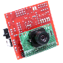
Introduction: Connecting Two OOBoards Together Using I2C
This instructable covers how to connect two OOBoards using I2C.
Step 1: Connecting to the I2C Network Bus
There are two I2C busses on the OOBoards, a local bus, and a network bus.
The OOPIC code is essentially an interpreted
language, ie the "code" is stored in EEPROM, and read/interpreted by
the microprocessor in real time. The EEPROM uses the LOCAL I2C bus to
communicate with the microcontroller. If you were to look at this
local bus on the oscilloscope, you would see constant chatter. On the OOBoards
boards, the local bus is what is connected to the I2C connector, this
isn't necessarily what we want.
The NETWORK bus is usually the bus that is used to communicate with
other devices/oopics, on the OOBoards this bus does not have a
connector. In order to access this bus, you must solder wires to pins
42 and 37 of the microcontroller (marked N_SDA, N_SCL on the schematic
respectively).
Step 2: Add the Pullup Resistors
Once SDA and SCL connections are made on each processor, the two boards can
be linked together by connecting SDA to SDA, SCL to SCL, and
connecting a common ground wire between the boards. You will also need
a pull-up resistor on each line (i used 12k, but thats just what I had
lying around).
Note that you only need one pullup resistor per line for a total of two resistors (not 4).
Step 3: Program the Slave
Dim SLAVE As New oDDELinkDim LED As New oDIO1Sub Main() 'set our I2C address to 2 (note, this must match the remote 'address we set in the master code) ooPIC.Node = 2 'setup an LED LED.IOLine = 5 LED.Direction = cvOutput 'now, link the output of our DDELink object to 'the LED, and turn it on...now automagically, the LED will blink SLAVE.Output.Link(LED) SLAVE.Operate = cvTrueEnd Sub
Step 4: Program the Master
Dim Master As New oDDELinkDim wire As New oWireDim hz1 As New oBitSub Main() 'link the 1 second timer to the a bit we can access 'this bit will now toggle once per second wire.Input.Link(ooPIC.Hz1) wire.Output.Link(hz1) wire.Operate = cvTrue 'this sets the I2C address of our local microcontroller 'the I2C interface is not active until an address is set ooPIC.Node = 1 'now we setup our DDELink object, our input is the bit hz1 'note that the object also has a .Output property that is used 'when we are in recieve mode Master.Input.Link(hz1) 'this is the I2C address of the remote microcontroller, note that 'in the slave code, we tell it to have an address of 2 Master.Node = 2 'ugh...this is the crappy part, this is the "address" of the DDELink 'object in the slave's memory space. In order to figure out this number, 'we need to open and compile the slave code, then goto View->Compiled Code. 'look for something like: 'L*.Construct.Begin ;Dim <name> as new oDDELink 'where * is any number, and <name> is the name of your DDELink object 'in your slave code. The line immediately below it should read something like: 'C0020:041 ;This.<name>.Address 'the number to the right of the ':' is the address of the slave DDELink object Master.Location = 41 'this tells the object that we will be sending data (ie, copy data from our .Input property 'to the slaves .output property (note, if you set this to recieve, it is the opposite) Master.Direction = cvSend 'turn it on, but nothing is happening yet... Master.Operate = cvTrue Do 'check to see if we are currently transmitting data If Master.Transmitting = cvFalse Then 'setting this value to 1 will cause the master to send the value to the slave 'note, this is automatically reset to 0 upon completion of transmission Master.Sync = 1 End If LoopEnd Sub


