

Introduction: Control Fluorescent Lights With a Laser Pointer and an Arduino


A few members of the Alpha One Labs Hackerspace do not like the harsh light given out by fluorescent fixtures. They wanted a way to be able to easily control the individual fixtures, perhaps with a laser pointer?
I got right on it. I dug out a pile of solid state relays and brought them to the Lab. I bought an Arduino Duemilenova and demonstrated the use of the LED Blink example sketch to actually blink a halogen lamp. I found some info on using LEDs as light sensors [1] and an Arduino sketch demonstrating the technique[2].
I found that the LEDs were not nearly sensitive enough - the laser had to point straight into the light emitting part, or the LED wouldn't register. So I switched to phototransistors. They are much more sensitive, and over a wider range of frequencies. With the proper filter over the transistor I could make it more sensitive to red light, and from a much wider range of angles to the sensor.
DISCLAIMER AND WARNING: This instructable deals with line (mains) voltage at 120 or 240 volts. Use common sense if you build this circuit - if you have a doubt about something, ask someone who knows. You are responsible for your (and others') safety, and compliance with local electrical codes.
Attachments

Step 1: The Sketch and Some Theory
I'll assume you know how to power your Arduino, and get a sketch compiled and loaded in.
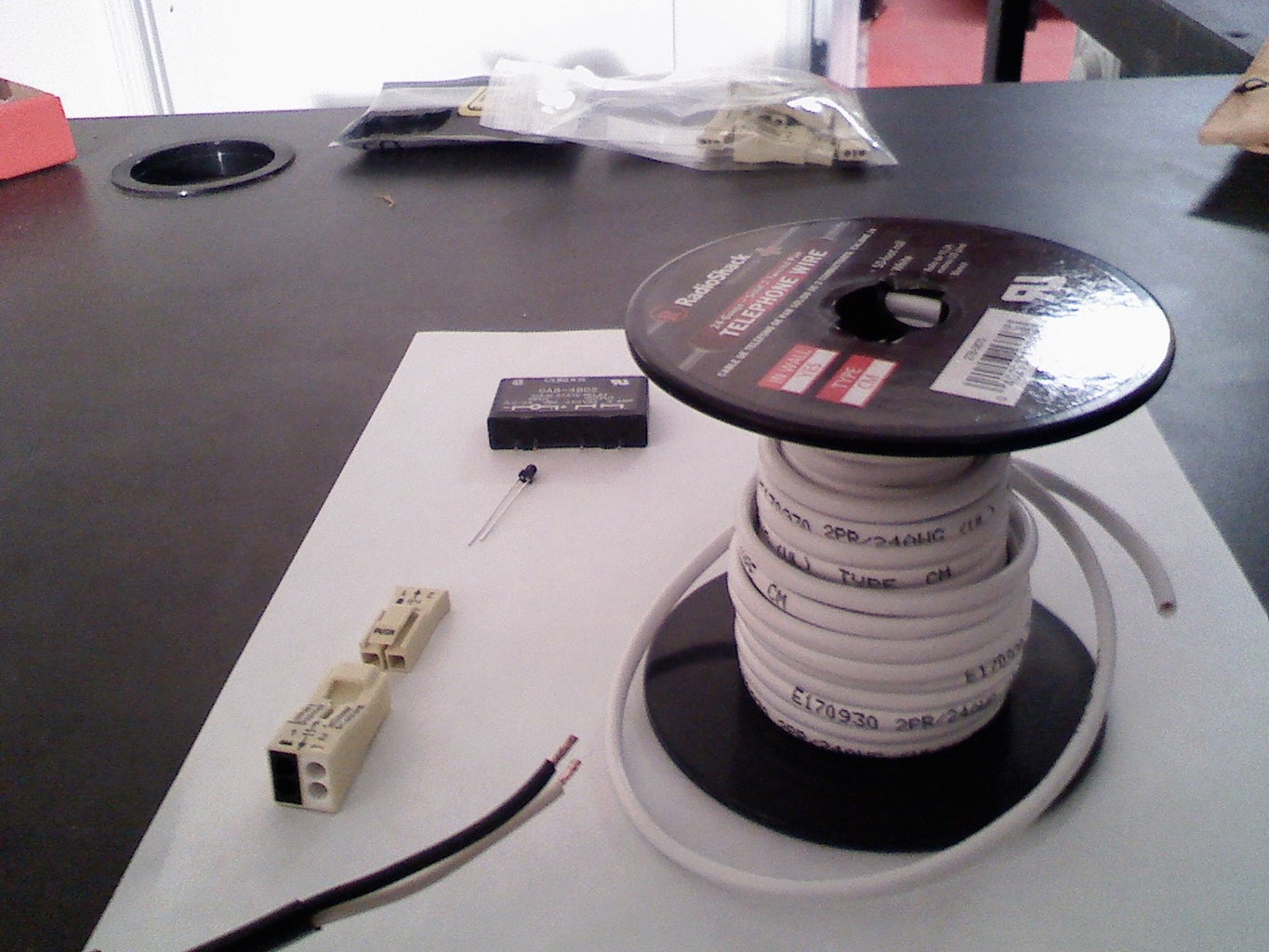
For each lamp I use telephone cable, since it's cheap, has four conductors, and I had a bunch laying around anyway. I used red for common +, black for ground, green for the phototransistor collector, and yellow for the relay control +.
A phototransistor passes an amount of current that varies with the amount of light falling on it. The Analog to Digital Converter (ADC) in the arduino measures the voltage at the pin relative to ground. I looked at the phototransistor data sheet and verified with a multimeter that the transistors pass 10mA at full light. Using Ohm's law, that's about 500 ohms at 5V,
To control the lamps I used a solid state relay module. These are relatively cheap at the current rating we needed, about $4 for up to 4A. Make sure to buy relay modules with a zero-crossing detector, especially if controlling anything inductive, like a fluorescent light, motor, or wall-wart transformer. Switching them on or off anywhere but the zero point could cause voltage spikes which at best will reduce the life of your appliance, and at worst start a fire.
Attachments
Step 2: Wiring the Lights


Have a look in the ceiling and decide where you will mount the Arduino controller. Remember that it will need a 7-12v poweer supply. Cut lengths of telephone wire (or cat5 or whatever) about two feet longer than the distance from the Arduino to each light you want to control.
Have a look at the connection from the power lines from the switch into the ballast. You might be able to order connectors (Newark Electronics sells the Wago 930 series, which is what we had). Then you won't need to cut existing wires and can remove the system if something goes wrong.
Solder the ground (black) to the relay input -, and the control (yellow) to relay input + (the color code in the picture is different from what I put on the front page, since I changed my mind about what would make sense).
Solder or screw on (depending on your relay) the black (hot) wire through the relay. Make sure to use heat shrink and electrical tape! Push the black wires into your connectors and the white (neutral) and ground (green) are just straight through from connector to connector.
The other end of the wires go to the Arduino as follows:
All the red wires (common cathode or collector) go to Analog 0 (port C0), and all the black to ground. Each green (anode or emitter) goes to pins 8-13 (port B 0-5) and the yellow wires go to the pins 2-7 (port D 2-7). Make sure that the green and yellow wires match up, since the sensor needs to control the proper relay! If you put the yellow into pin 2, the green from the same fixture goes to pin 8.
Step 3: Testing the Sketch and Design Notes
In this step I'll talk about some of the trials and tribulations that I encountered on the way, and how I worked through them, in the hope that it will be useful. Fell free to skip to the next step if Science Content isn't your thing :-)
The first step was deciding whether to use capacitive sensing or resistive sensing. Resistive sensing is connecting the sensor through a resistor to one of the analog pins and doing analogRead and comparing against a threshold. This is simplest to implement, but takes lots of calibration.
The theory of capacitive sensing is that when reverse biased (- to the + lead and vice versa), an LED will not allow current to flow, but electrons will collect on one side and leave the other side, effectively charging a capacitor. Light falling on the LED at the frequency it normally emits will actually cause a smal current to flow, which discharges this capacitor.
So if we charge the LED 'capacitor' and count how long it takes to discharge through a resistor, we get a rough idea of how much light is falling on the LED. This actually worked out to be more reliable across different devices, and even works for phototransistors! Since we're not doing a precise lumen measurement, and the laser pointer should appear a lot brighter than ambient, we just look for a thresholded discharge time.
The other important part of this adventure is debugging. For those familiar with programming non-embedded systems, a popular method is to add print statements at critical points in the code. This also applies to embedded systems, but when every microsecond counts, the amount of time to Serial.write("x is "); Serial.writeln(x); is actually quite significant, and you may miss a lot of events in the process. So remember to always put your print statements outside of critical loops, or any time you expect an event. Sometimes blinking an LED is enough to let you know you got to a certain point in the code.
Step 4: Adding Web Control

If you looked through the sketch, you noticed that I also read the serial port, and act on a few single character commands. The 'n' character turns on all the lights, and 'f' turns them off. The numbers '0'-'5' toggle the state of the light connected to that digital output.
So you can easily throw together a CGI script (or servlet, or whatever web technology floats your boat) to control your lights remotely. The Serial.writes also output whenever a light is changed from user input, so the page can have Ajax updates to show the current state.
Another thing I'm going to experiment with is detecting motion in a room. People reflect light, and as they move that light will change. That's the 'delta' part of the write statements I have.
Participated in the
Arduino Contest


![Tim's Mechanical Spider Leg [LU9685-20CU]](https://content.instructables.com/FFB/5R4I/LVKZ6G6R/FFB5R4ILVKZ6G6R.png?auto=webp&crop=1.2%3A1&frame=1&width=306)


