

Introduction: Control a Relay Over the Internet Via Arduino With Teleduino


What would make a relay even better? How about controlling a relay over the internet from anywhere in the world? Yea!
This process is made really simple using the Teleduino sketch for your ethernet enabled Arduino. Haven't heard of Teleduino? That's cool, you may want to take a look at Arduino Control via a Web Service with Teleduino to get yourself started.
This tutorial will guide you through the process of attaching a 5V relay to your Arduino, and provide some example Teleduino API calls to:
- Define the pin mode of a pin
- Turn on the relay
- Turn off the relay
- Toggle the relay
Let's get started!
Step 1: Parts Needed and Circuit Diagram


You need the following parts to complete this tutorial:
- Breadboard (optional, but makes prototyping much easier)
- 5V Relay (the relay in the image has had legs added so that it can be connected to a breadboard)
- 1K Resistor
- 1N4001 Diode
- 2N2222 Transistor
- Some hookup wire
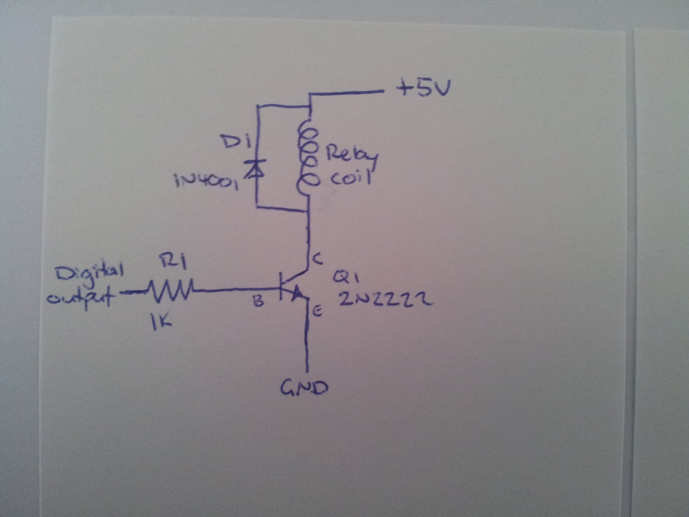
Circuit Diagram
Take a peak at the attached circuit diagram. It shows how the components needs to be connected. You may need to look at the datasheet for your relay to know which pins are used for the coil.
The additional image illustrates the pin layout of your 2N2222 transistor. This will help you understand what pin needs to connect to which part of the circuit.
Time to get this hooked up!
Step 2: Put Circuit Together


Image 1
On this particular relay the coil pins are right next to each other, which makes things pretty easy. Ensure that you check the datasheet for your particular relay to work out which pins are used for the coil.
Image 2
The Diode and Transistor has been added. Note the direction of the Diode and the Transistor - this is very important! The circuit will not work if the direction is incorrect (and may cause irreversible damage to your Arduino!). Check your component layout against the circuit diagram in Step 1.
Image 3
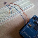
Add the Resistor and Hookup Wire. There are three wires that need to be connected to your Arduino (5V, GND and Pin 4).
Image 4
Shows the correct way to connect the relay circuit to your Arduino board.
Let's make the relay click!
Step 3: Control Relay Via the Teleduino API
Here are some example API calls that you can use to control your relay. You need to replace {key} with the unique API key you obtained when you completed the instructable Arduino Control via a Web Service with Teleduino. Just chuck the URLs into your browser's address bar and you should see some magic happen on that relay.
Define the pin mode of digital pin 4 (Must be done once per boot prior to setting digital outputs. 'pin=4' mean pin 4, 'mode=1' means OUTPUT):
http://us01.proxy.teleduino.org/api/1.0/328.php?k={key}&r=definePinMode&pin=4&mode=1
Set the output of digital pin 4 to HIGH ('pin=4' means pin 4, 'output=1' means HIGH):
http://us01.proxy.teleduino.org/api/1.0/328.php?k={key}&r=setDigitalOutput&pin=4&output=1
Set the output of digital pin 4 to LOW ('pin=4' means pin 4, 'output=0' means LOW):
http://us01.proxy.teleduino.org/api/1.0/328.php?k={key}&r=setDigitalOutput&pin=4&output=0
Toggle the output of digital pin 4 ('pin=4' means pin 4, 'output=2' means toggle):
http://us01.proxy.teleduino.org/api/1.0/328.php?k={key}&r=setDigitalOutput&pin=4&output=2
Make it click!
Step 4: Further Reading
Controlling a relay is just a very simple example of what can be achieved by using the Teleduino Arduino library/sketch.
To view the full API reference manual, take a look at http://www.teleduino.org/rtfm/api/328.php.
Have fun!

Participated in the
Arduino Challenge


