

Introduction: Controlling 2 Servos Using Analog Joystick.


Hello guys ,
this is my first instructable and in this post I'm sharing how to use Analog Joystick to control Servos using Arduino UNO.
I'll try to explain it as simple as possible hope you like it.
Step 1: Gathering Parts


- 1 x Arduino UNO. (Amazon US / Amazon EU / Banggood)
- 2 x Servos. (Amazon US / Amazon EU / Banggood)
- 1 x Analog Joystick. (Amazon US / Amazon EU / Banggood)
- 1 x Breadboard. (Amazon US / Amazon EU / Banggood)
You can use any Analog Joystick which is available in market which already have labels on pins so it is easy to use them .
I have used salvaged part from an old PS2 controller which has 2 joysticks.
Step 2: Preparing the Analog Joystick.


You can use the one that is available in market which has labelled pins and are easy to use or you can save couple of bucks and salvage old ones from gaming controllers which have 2 inside them .
I have shared the pics of the one I have and also I have labelled the pins , which I found out by backtracking the coper trace on the PCB ,
here two pots are used in each joysticks one for x axis and other for y axis we use the middle terminals of these pots to control the servos .
other two pins are power and ground pins where we apply 5volt and Ground.
the pins which are not labelled in the corner are the button pins which are not needed on this project.
basically all sticks have same configuration.
Now once you have figured out pins of your sticks we can move to next step which is connecting the circuit.
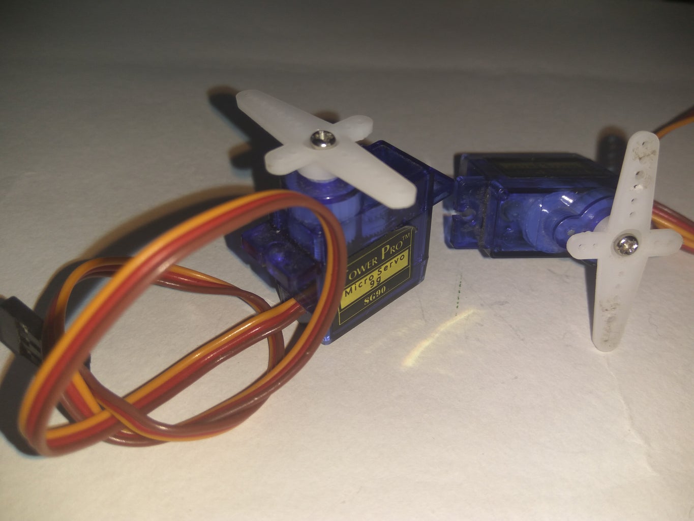
Step 3: Servos.


Servos are geared motors which are slow but have high torque and rotate only upto 180° .
A normal servo has 3 pins :
1. Yellow/Orange which is signal pin and connects to PWM pins on Arduino.
2. Red which is the power pin where we provide +5v which is connected to +5v of Arduino.
3. Brown/Black which is Ground pin and I'd connected to GND pin of Arduino or -ve terminal of battery .
In this project we are using 2 Servos one connected to pin no. 3 and other to pin no. 5 .
I have used micro 9g servo but any would work .
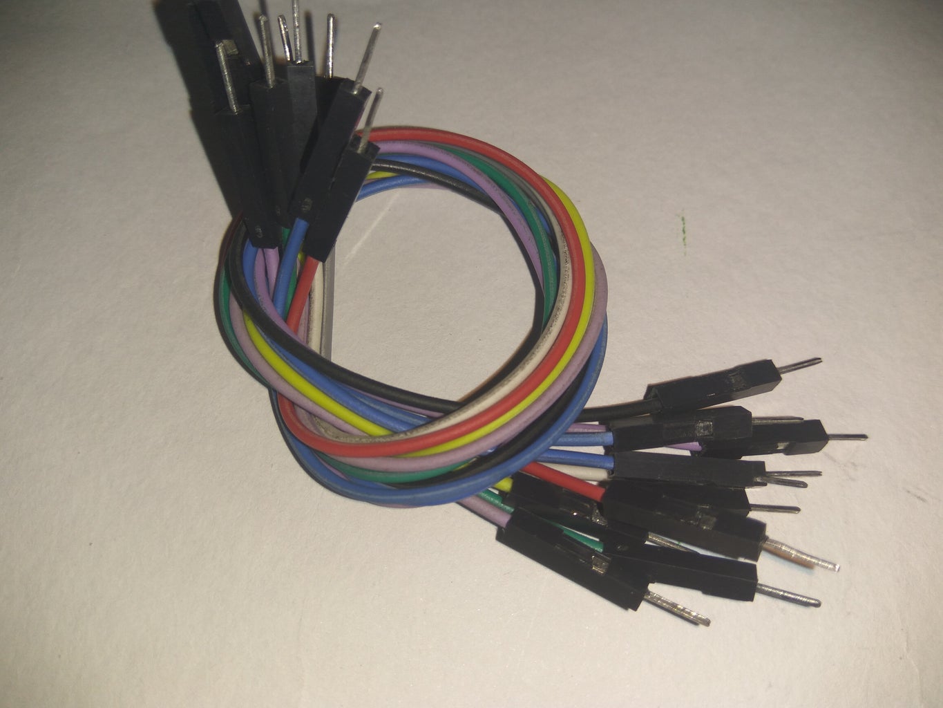
Step 4: Making Connections.


Follow the circuit diagram to make the connection of the servos .
the red wire goes to 5v and brown wire goes to GND
signal pin of one servo goes to 3 and other servo goes to 5 of Arduino .
next connect the Analog Joystick
it has a + and - terminals that goes to 5v and GND respectively.
the X axis pin goes to A0 or Analog 0 pin of Arduino and Y axis goes to A1 or Analog 1 pin .
next we will upload the code.
Step 5: Writing and Uploading Code.
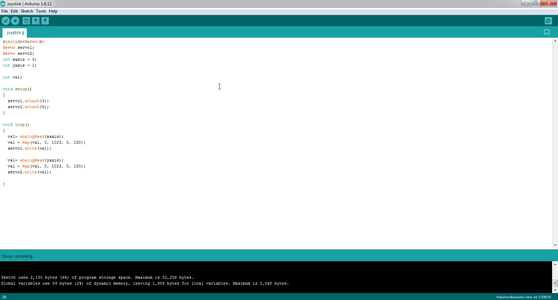
The code is simple and similar as the Knob example of the servo library in Arduino IDE.
#include
Servo servo1;
Servo servo2;
int xaxis = 0;
int yaxis = 1;
int val;
void setup()
{
servo1.attach(3);
servo2.attach(5);
}
void loop()
{
val= analogRead(xaxis);
val = map(val, 0, 1023, 0, 180);
servo1.write(val);
val= analogRead(yaxis);
val = map(val, 0, 1023, 0, 180);
servo2.write(val);
}
copy the above code and paste in Arduino IDE and compile .
then upload the code and the servos should move into center position then you can control the servos using the joystick .
the other Joystick can control 2 more servos . you just have to connect the servos to PWM pins on Arduino and modify the code .
The code is easy to modify and anyone with basic Arduino knowledge can do it.
Hope you like the Project and if you have any questions feel free to ask.
Thank you.


