

Introduction: Controlling Motors With Arduino


This is a simple Instructable to tell you how you can control DC motors with an Arduino. It was requested by a fellow user so I thought I would go ahead and throw something together. I will be using a simple h-bridge IC with some Arduino code that should be compatible with any Arduino or Arduino clone. I will assume that you already have the Arduino IDE downloaded and installed and you know how to upload sketches to your board.
Step 1: Parts
- H-Bridge IC
- Arduino Leonardo
- Breadboard
- Various Jumper wires
- 10K potentiometer
- two pushbuttons
- four 10k resistors
Step 2: The Circuit
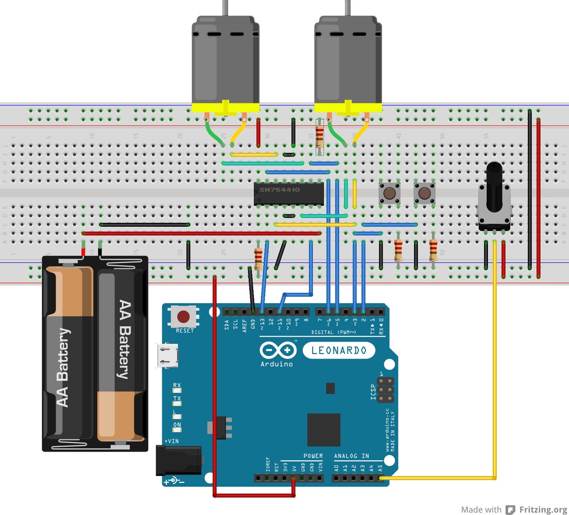
This is a fairly simple circuit. We will use two push buttons to control the direction of the motors. The potentiometer will be used to allow us to control the speed of the motors, mapping the analog input of the potentiometer(0-1023) to the PWM duty cycle(0-255) used to set the speed. Each motor requires two digital control pins which are used to set the direction. When one pin is high and the other is low, the motor will go one way, when you switch the state of each pin, the motor will spin in the opposite direction. Setting both pins low will cause the motor to stop. The pins on the H-Bridge are connected to the following...
H-Bridge
1,2EN ---> To +5V through 10k resistor
1A---> Arduino pin 13
1Y---> Motor 1 positive lead
GND---> Common ground
GND---> Common ground
2Y---> Motor 1 negative lead
2A---> Arduino Pin 11
VCC2---> Motor Power supply
VCC1---> Logic Supply +5V
4A---> Arduino Pin 6
4Y---> Motor 2 positive lead
GND---> Common ground
GND---> Common groun
3Y---> Motor 2 negative lead
3A---> Arduion Pin 5
3,4EN---> To +5V through 10k resistor
The potentiometer has three pins on it, one of the outside pins is connected to ground, the other outside pin connected to +5V. The middle pin is the signal pin and is connected to analog pin A5 on the Arduino. The two push buttons are connected to digital pins 2 and 3 on the Arduino as shown in the poorly drawn Fritzing image.
The two motors are connected to the Y pins on the H-Bridge. One motor is connected to 1Y and 2Y, the other is connected to 3Y and 4Y. It is OK to switch up 1 and 2 or 3 and 4, they can always be switched around to fix the direction.
Step 3: Arduino Code

The Arduino code is straight-forward, the setup function sets the outputs and inputs. The loop is just a continuous function sets the PWM based off of the input from the potentiometer, then it checks the buttons. If one button is pressed then the motors will run in one direction. If you other button is pushed then it will go in the opposite direction. It neither button is pushed then the motors will remain motionless. I hope this will be of some help to some people. It's a little quick and dirty but I hope that it is not too hard to understand.


