

Introduction: Controlling the Direction and Speed of a DC Motor With LabVIEW and FPGA


A simple project that allows you to control an DC motor using FPGA and LabVIEW.
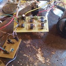
Step 1: Hardware Design


In order to be able to control the direction and the speed of a DC motor I design a H bridge with complementary mosfet transistors (IRF3205+IRF4905) and for drivers I choose MAX628 provided by Maxim Integrated.
The H bridge work in this way:
-the high side P-channel mosfet transistors work only on/off;
-the low side N-channel mosfet transistors work with 15 Khz PWM for speed control.
This design allow to operating voltage up to 30 V and a current up to 10 A (for more current you should use a heat sink or parallel mosfet transistors).
If you want to use this design on higher operation voltage you should do the next changes:
- change all mosfet transistors with other which have Vds compatible with the voltage desired;
-change the LM7812 regulator, or supply 12V in another way because this voltage is used to supply the drivers for mosfet transistors and cannot be more than 18V, or you risk to damage the mosfet transistors.
In order to control the motor you should do this steps:
- for rotating in one way, the inputs called with 1 and 4 need to be set to 5 V (or 1 logic) for maximum speed or for speed controlling mode the input 1 need to be set to 5 V (or 1 logic) and the input 4 gets a PWM signal with duty cycle variable (the inputs 2 and 3 need to be set to 0 logic or grounded);
-for rotating in the other way, the inputs called with 2 and 3 need to be set to 5 V (or 1 logic) for maximum speed or for speed controlling mode the input 3 need to be set to 5 V (or 1 logic) and the input 2 gets a PWM signal with duty cycle variable (the inputs 1 and 4 need to be set to 0 logic or grounded);
- for brake the motor you need to set the low side or high side mosfet transistors to 5 V (or 1 logic), but only high or low side, the other should be set to 0 logic or grounded. This method short circuit the motor and cause the brake.
Step 2: Software Design
The software was written in VHDL language using the ISE tools.
The Nexys 3 board read ASCII letters from PC via RS232 protocol and with if statements set the motor operation.
(I am electronics engineer not a programmer, maybe the the software is little rusty but works very well)
The VHDL project contains:
-clock divisor from 100 MHz to 50 Mhz;
-serial RX and TX module;
-PWM module;
Attachments

Step 3: LabVIEW Interface Design

Attachments
Step 4: Video During the Tests
Thank you!


